26 – Control CS 320 / Rev.D 1.01 Control CS 320 / Rev.D 1.01 – 27
7. Setting the limit positions
7.1 7.1 Checking the drive / travel direction Checking the drive / travel direction
Change to adjustment mode
Press the (P) button until ADJUSTMENT appears.Press the (P) button until ADJUSTMENT appears.
Checking the drive direction
Press the (+) button. The door must open. Press the (+) button. The door must open.
Press the (-) button. The door must close.Press the (-) button. The door must close.
If this is correct, proceed to setting the limit positions.
Otherwise, change the direction of travel.
Changing the direction of travel
Press and hold the buttons (+) and (–) simultaneously for Press and hold the buttons (+) and (–) simultaneously for
morethan5seconds.Thedisplayshows“LEFTROTFIELD”. morethan5seconds.Thedisplayshows“LEFTROTFIELD”.
Any limit positions that were saved will have been deleted.
Proceed with the setting the limit positions.
7.2 7.2 Setting the mechanical limit switchesSetting the mechanical limit switches
Change to adjustment mode
Press the (P) button until ADJUSTMENT appears.Press the (P) button until ADJUSTMENT appears.
Setting the UP and DOWN limit positions
REFERENCE
Setting the limit positions is described in the separate
documentation for the mechanical limit switches.
Exit adjustment mode by pressing the (P) button.Exit adjustment mode by pressing the (P) button.
Note
The system does not exit adjustment mode automatically.
Exit adjustment mode by pressing the (P) button in order to
change to normal mode.
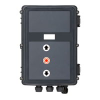
7.3 7.3 Setting the electronic end position Setting the electronic end position
system using the setting buttons on the system using the setting buttons on the
circuit boardcircuit board
Change to adjustment mode
Press the button (P) for approx. 5 seconds. Press the button (P) for approx. 5 seconds.
TheredLEDashesslowly.TheredLEDashesslowly.
Setting the UP end position
Drive the door to the desired UP end position by pressing Drive the door to the desired UP end position by pressing
the (+/–) buttons.the (+/–) buttons.
Save end position by pressing the (P) button and Save end position by pressing the (P) button and
additionally also the (+) button. additionally also the (+) button.
TheredLEDashesrapidlyforapprox.1second.TheredLEDashesrapidlyforapprox.1second.
Setting the DOWN end position
Drive the door to the desired DOWN end position with the Drive the door to the desired DOWN end position with the
(+/–) buttons.(+/–) buttons.
Save end position by pressing the (P) button and Save end position by pressing the (P) button and
additionally also the (–) button. additionally also the (–) button.
TheredLEDashesrapidlyforapprox.1second.TheredLEDashesrapidlyforapprox.1second.
The adjustment mode is automatically exited.
The red LED goes out.
Note
− The adjustment mode is automatically exited after approx.
7 minutes, if no button is pressed.
− Normal operation is not possible until both end oth end positions
have been learned through the initial calibration.
− If an end positioposition is to be corrected, the ADJUSTMENT
mode can be exited by presby pressing the (P) button after
learning the special end position.
− After programming the limit switches, the system run-time
is learned automatically. The controller functions are the
same as in automatic mode.