CP5 • System description
CP_SEM_60-00-60.001 17
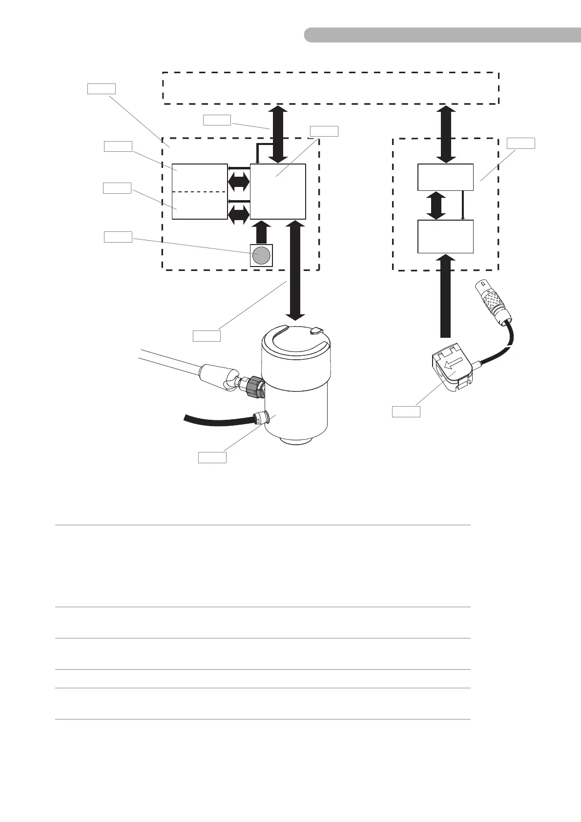
Fig. 2: Diagram
24V
5V
5V
5V
LCD with
Touch screen
HKD 0327
HKR 0325
Digiflow
Mini-1
HSF 0803
E/P pack
Pump control panel Sensor module
flow measurement
Assembly Component contains the following service-relevant assemblies/components:
A Pump control panel ◗ Circuit board Display HKD 0327 (A 6)
◗ Circuit board CPU HKR 0325 (A 5)
◗ Circuit board LCD with touch screen (A 4)
◗ Shaft encoder (A 14)
◗ Fan
◗ Connection cable E/P pack (A 10)
See
„Assembly overview – Con-
trol panel“ on page 19.
B Drive unit ◗ Circuit board Motor control ZKR 0801
◗ Connection cable pump control panel (B 1)
C Emergency system with drive
shaft
◗ None, replace the emergency system in the case of a fault.
D Flow sensor ◗ None, replace the sensor in the case of a fault.
E Sensor module for flow
measurement
◗ Circuit boards
 Loading...