4 -10
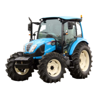
① Adjustment of Lift rod and Upper link
Lift rod (LH)
Lift rod (RH)
Upper link
Lift rod handle
Adjustment
range
Classification Lift rod Upper link
left
495~635 mm
( 19.5 ~ 25.0 in. )
550 ~ 855 mm
( 21.7 ~ 33.7 in.)
right
495~635 mm
( 19.5 ~ 25.0 in.)
z Do not adjust the lift rod and upper link over the
described range as below.
z Lift rod (RH)
- Lift up the lift rod handle and turn left or right to
adjust the length.
- Lock the lift rod handle to the lower part after
adjusting.
z Lift rod (LH)
- Remove the upper lift rod pin and turn the
upper part of the lift rod.
z Upper link
- Lift up the lock spring to release the handle and
turn the upper link by using the handle.
- Apply the lock spring after adjusting.
①
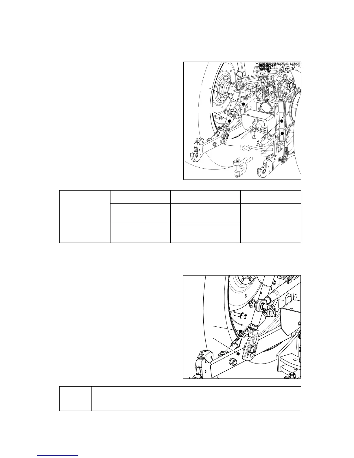
② Adjustment of stabilizer (optional)
- Check link type
z Pull up the link pin(1) and pull/push the lower
link(2) with checking the swinging clearance.
z Insert the link pin(1) into the hole and let it
tightened firmly by locking spring.
▶When adjusting the stabilizer’s length, adjust the implement’s swinging clearance to
be 20~40mm (0.8~1.6 in.) left and right.
Notice
②