3 -42
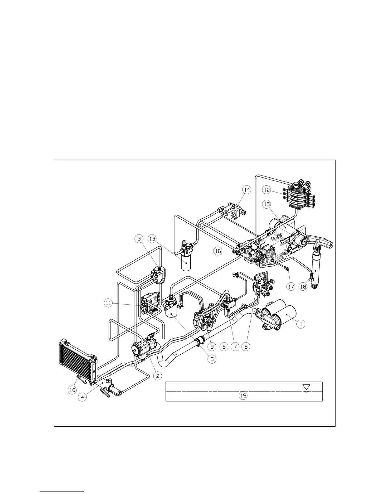
(7) Hydraulic System Diagram
1. Hydraulic oil filter
2. Hydraulic pump
3. Steering unit
4. Steering cylinder
5. Power shuttle filter (if fitted)
6. Sequence valve
7. Oil cooler valve
8. T/M control valve
9. Power shuttle valve
(if fitted)
10. Oil cooler
11. Front loader valve
(Opt.: Front outlet valve)
12. Remote control valve
13. In-line filter (if fitted)
14. Leveling control valve
(optional)
15. Hydraulic lift housing
16. EHL valve
17. Safety valve
18. Hydraulic lift cylinder
19. Oil tank (Transmission case)
② PSS+EHL