Lynx NGT-9000s
Installation Manual
2.3.2.3.1 Directional Antenna Cables
The directional antenna installation is optional and used only for models with Traffic Alert System (TAS).
1. The directional antenna requires three cable assemblies; sum (Sigma Port), bit probe (Probe Port)
and difference (Delta Port). Cable attenuation for the sum and difference ports must not exceed 1.5
dB. Attenuation for the bit probe cable must not exceed 6 dB. VSWR, on cables attached to the sum,
bit probe, and difference ports, must not exceed 1.5:1. (See paragraph 1.6 for antenna cable vendors
and specifications.)
2. At the antenna, each connector has an identifying color band. To ensure the cables are connected to
the correct port, affix the following marking at the termination points of each cable:
• Sum (Sigma) Port The Sum (Sigma) port is the forward antenna connector. It is marked
with a blue band
. Fabricate the sum antenna cable with a TNC
connector at each end. Affix a blue marking
band on each connector.
At the NGT-9000, the sum port (A4) is identified with blue marking.
• Bit Probe Port The Bit Probe port (A1) is the center antenna connector. Fabricate the
probe cable with a BNC connector at each end.
• Difference (Delta) Port The Difference (Delta) port is the rear antenna connector. It is marked
with a red band
. Fabricate the difference antenna cable with a TNC
connector at each end. Affix red marking
band on each connector. At
the NGT-9000, the difference port (A2) is identified with red marking.
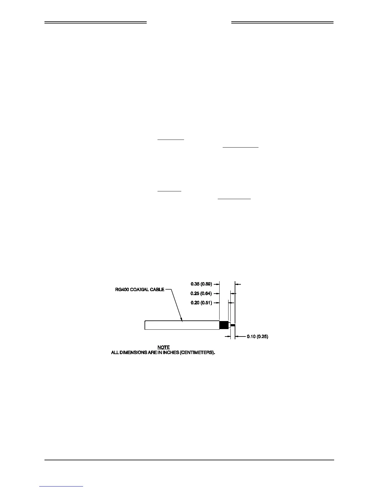
2.3.2.3.2 Coax Cable Assembly Guidelines
The cable manufacture’s cable prep specifications take precedence over the guidance provided in this
manual. Use the following procedures to assembly straight or right angle coax connectors.
1. Cut back outer plastic sheath and inner insulator to expose the copper shield and copper core as
shown in Figure 2-8.
2. Slide Crimp Contact over coaxial cable.
Figure 2-8: Coax Cable Preparation
0040-17001-01 Installation Page 2-17
Revision A January 15, 2015
 Loading...