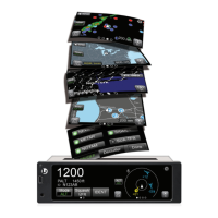
Lynx NGT-9000s
Installation Manual
1.6 SPECIFICATIONS
Table 1-3: Specifications for Lynx NGT-9000s
PART NUMBERS:
9029000-20000
CERTIFICATION:
USA (FAA): TSO-C112d, C113a, C145c, C147, C154c, C157a, C166b, C195a.
See paragraph 1.7 for specific TSO information.
Listed are current authorizations at time of publication, contact Field Service Engineering for
latest certification information
ADVISORY CIRCULARS:
AC20-21-46, AC20-115B, AC20-152, AC20-165A, AC20-172A
RTCA COMPLIANCE:
Environmental Category: DO-160G (See Environmental Qualification Form in Appendix B.)
Software Category: DO-178B, Design Assurance Level C
Hardware Category: DO-254, Design Assurance Level C
Other: DO-181E, DO-197A, DO-229D, DO-260B, DO-267A, DO-282B, DO-317A,
ARINC 718A-4 and SAE AS8034B.
COMPLIANCE:
ATC transponder functionality: 14 CFR 91.215, 91.217, 91.413
ADS-B Out functionality: 14 CFR 91.225, and 91.227
The Lynx NGT-9000s has been shown to meet the requirements in TSO-C166b and meets
the requirements of 14 CFR 91.227 installed in accordance with these installation
instructions.
SIZE:
Case
Width 1.48 inches [12.83 cm] MAX
Height: 5.75 inches [7.42 cm] MAX
Depth*: 8.99 inches [3.81 cm] MAX
Bezel
Width 6.25 inches [13.44 cm] MAX
Height: 1.8 inches [7.62 cm] MAX
* Does not include connectors.
Note: Unit Fits into a “MARK width” panel.
WEIGHT:
Nominal 1.0 Lbs (0.5 kg) Maximum 4.0 Lbs (0.8 kg)
CHASSIS GROUND:
Bonding impedance between aircraft ground and the Lynx NGT-9000s Chassis must be less
than 2.5 milliohms.
POWER REQUIREMENTS:
+14.0 VDC nominal. 19.0 watts nominal (24.0 watts maximum)
+28.0 VDC nominal. 19.0 watts nominal (24.0 watts maximum)
ELECTRICAL CONNECTORS:
• 78 position d-subminiature connector receptacle (shell size 5) with swaged float plate.
Connector insert per MIL-DTL-24308, Appendix A, Figure A-5, Arrangement 2.
Connector insert shall accommodate 22D removable crimp contacts (socket) per
M39029/57-324, or equivalent.
• RF Connectors: 5W5 Coax D-Sub
• Mini-B USB: Maintenance Port
INTERFACE (S):
• ARINC 429
• RS-422
• RS-232
• Discrete Input/Outputs
• RF Suppression Bus
• I
2
C serial interface (detachable configuration module interface)
Note: Refer to Appendix A for signal names and characteristics
Page 1-12 General Information 0040-17001-01
January 15, 2015 Revision A
 Loading...