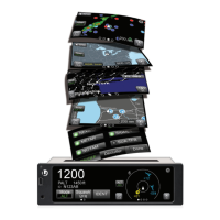
EasyManuals Logo

Lynx NGT-9000 User Manual

Lynx NGT-9000
182 pages
To Next Page IconTo Next Page
To Previous Page IconTo Previous Page
Page #161 background imageLoading...
Page #161 background image
Lynx NGT-9000s
Installation Manual
A.4 [J1 CONNECTOR]
PIN 1
Signal Name:
PWR_14_28VDC_IN
Signal Function:
+ 14/28 VDC Power IN 1
Electrical Characteristics:
30.0 watts maximum average
Connection:
Aircraft 28V BUS.
22 AWG wire
Comments:
PIN 2
Signal Name:
PWR_14_28VDC_IN
Signal Function:
+ 14/28 VDC Power IN 2
Electrical Characteristics:
30.0 watts maximum average
Connection:
Aircraft 28V BUS.
22 AWG wire
Comments:
PIN 3
Signal Name:
Ground
Signal Function:
14/28 V Power Return 1
Electrical Characteristics:
--------
Connection:
Aircraft 14 or 28V Return BUS
22 AWG wire
Comments:
PIN 4
Signal Name:
Ground
Signal Function:
14/28 V Power Return 2
Electrical Characteristics:
--------
Connection: Aircraft 14 or 28V Return BUS
22 AWG wire
Comments:
PIN 5
Signal Name:
ALT_IN_A1
Signal Function:
Gilham Altitude Encoder
Electrical Characteristics: +30 V input max, < 1 mA sourced per line
Frequency: 20 Hz, Source Z: > 10 k per line
Max Capacitance: < 20 pF per line
Connection:
See paragraph A.2.4
24 AWG wire
Comments:
0040-17001-01 Appendix A Page A-9
Revision A January 15, 2015

Table of Contents

Other manuals for Lynx NGT-9000

Questions and Answers:

Question and Answer IconNeed help?

Do you have a question about the Lynx NGT-9000 and is the answer not in the manual?

Lynx NGT-9000 Specifications

General IconGeneral
BrandLynx
ModelNGT-9000
CategorySecurity System
LanguageEnglish

Related product manuals