169441 44 Revision D
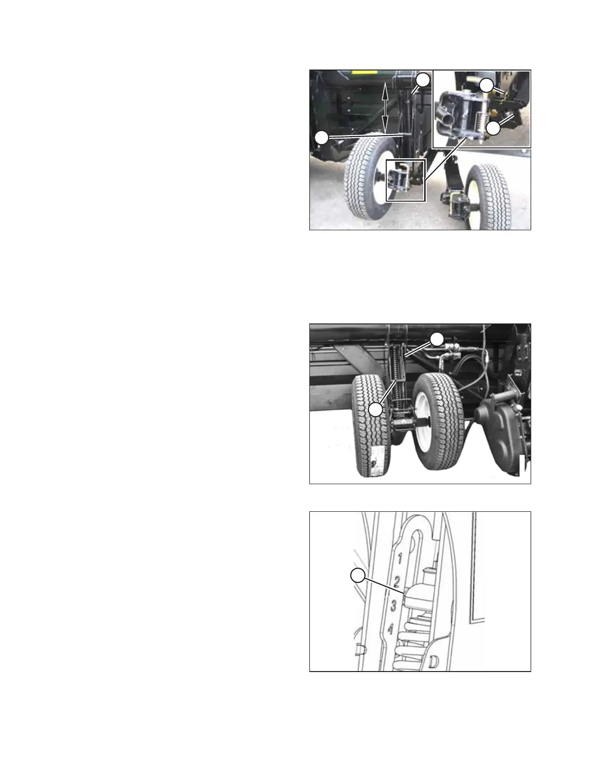
Figure 3.20: Right Wheel
4. Remove hairpin (A) from the latch on the right wheel
assembly.
5. Disengage latch (B), lift the wheel out of the hook, and
place the wheel on the ground as shown.
NOTE:
This reduces the weight of the assembly and makes
adjusting the wheel position easier.
6. Lift the left wheel slightly to support the weight, and pull
handle (C) upwards to release the lock.
7. Lift the left wheel to the desired height and engage the
support channel in slot (D) in the upper support.
8. Push down on handle (C) to lock it.
9. Lift the right wheel back into field position and ensure
latch (B) is engaged.
10. Secure the latch with hairpin (A).
Figure 3.21: Left Wheel
11. Support the wheel weight by lifting it slightly with one
hand, and pull up on handle (A) to release the lock.
12. Lift the wheels to the desired height, and engage the
support channel into slot (B) in the upper support.
13. Push down on handle (A) to lock it.
Figure 3.22: Load Indicator
14. Lower the header to the desired cutting height using the
windrower controls and then check load indicator (A).
OPERATION