OPERATING CONTROLS AND PROCEDURES 14000 OPERATOR MANUAL
3-50
Published 03-29-17, Control # 064-23
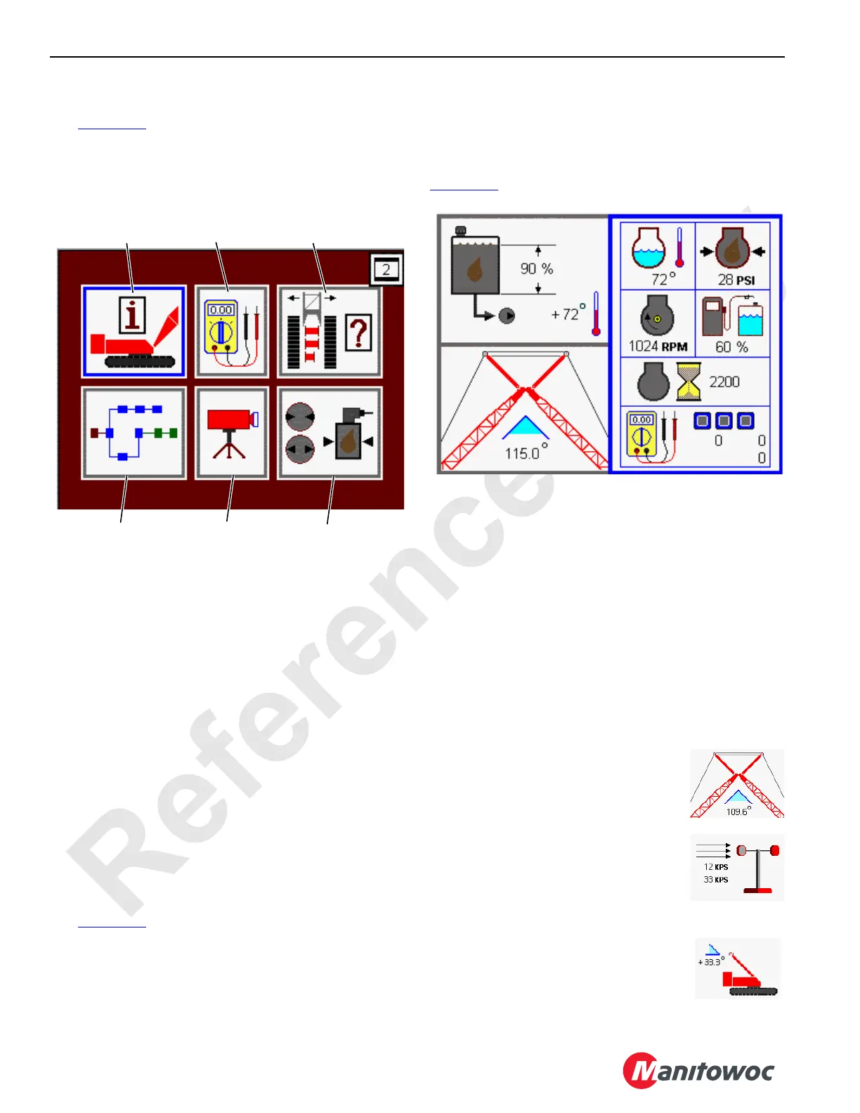
Menu Screen
See Figure 3-40 for the following procedure.
The Menu screen is the base screen for the crane system.
All other screens must be entered from this screen. Exiting
from any screen will return to the Menu screen.
The Menu screen shows six screen icons:
1. Information Screen icon
2. Diagnostic Screen icon
3. Function Mode Screen icon
4. CAN Bus Screen icon
5. Camera Screen icon
6. Pressure Test and Calibration Screen icon
The Menu screen operates on one level only.
• Use Select buttons to highlight icon that represents the
screen to be entered. Press the Enter button to go to
selected screen.
• To return to Menu screen, press Exit button until Menu
screen appears.
Information Screen
See Figure 3-41 for the following procedure.
Information screen shows all the general crane information
required for viewing during normal operation. The screens
contain three data boxes which may be individually tailored
to show the information items appropriate for the current
crane application.
When crane configuration is selected, the information
screen appears with engine data box on right side and
previously selected items on the left side as shown in
Figure 3-41
.
The Information screen operates on three levels:
Level 1— Selected data box highlighted blue. Use Select
buttons to highlight the data box to change.
Level 2 — Selected data box highlighted red. Use Select
buttons to choose the information item to be shown in the
highlighted data box.
Level 3 — Selected data box highlighted green (if
applicable). Use Select buttons to alter the information
displayed in the highlighted data box.
The crane information items currently available (if equipped)
for the two smaller data boxes on the left side of the screen
are as follows:
Boom to Luffing Jib Working Angle
Boom to luffing jib icon displays the boom
to jib working angle between center line of
boom and center line of luffing jib.
Wind Speed Indicator
Wind speed icon displays steady wind
speed and maximum gust wind speed. The
indicator is reset with Confirm button in
level 3.
Mast Angle
Mast angle icon displays mast angle in
degrees mast is positioned above transport
position.
FIGURE 3-40
CAN Bus
Screen
Diagnostic
Screen
Camera
Screen
Function Mode
Screen
Pressure Test and
Calibration Screen
14COM3-27-2
Information
Screen

 Loading...


