Manitowoc Published 03-29-17, Control # 064-23 3-21
14000 OPERATOR MANUAL OPERATING CONTROLS AND PROCEDURES
C – Indicators
See Figure 3-8 for the indicators.
C1. Fuel Level
Fuel level indicator is located in circular gauge in front panel.
Indicates amount of fuel remaining in fuel tank.
C2. Engine Coolant Temperature
See engine manual for operating specifications.
C3. Engine Oil Pressure
See engine manual for operating specifications.
C4. Battery Voltage
Indicates condition of battery charging system.
C5. Drum Rotation Indicators
Pin-type actuators located under all drum handle covers.
They move UP and DOWN to signal the operator, by feel,
that corresponding drum is turning. Indicator movement
corresponds to drum speed.
C6. Rear View Mirrors
Adjustable rear view mirrors mounted on operator’s cab and
at right front side of rotating bed allow operator to view rear
of crane. Mirrors can be rotated inward for shipping.
C7. Boom Angle Indicator
Shows the angle of boom in degrees above horizontal. The
boom, luffing jib, and mast angles can be viewed on Rated
Capacity Indicator/Limiter display or Main display.
See Figure 3-9
for identification of various boom and luffing
jib angles.
C8. Cab Beacon (optional)
The beacon rotates with a flashing amber light and alarm
whenever Rated Capacity Indicator/Limiter system is ON
and the crane’s capacity is near an overload condition.
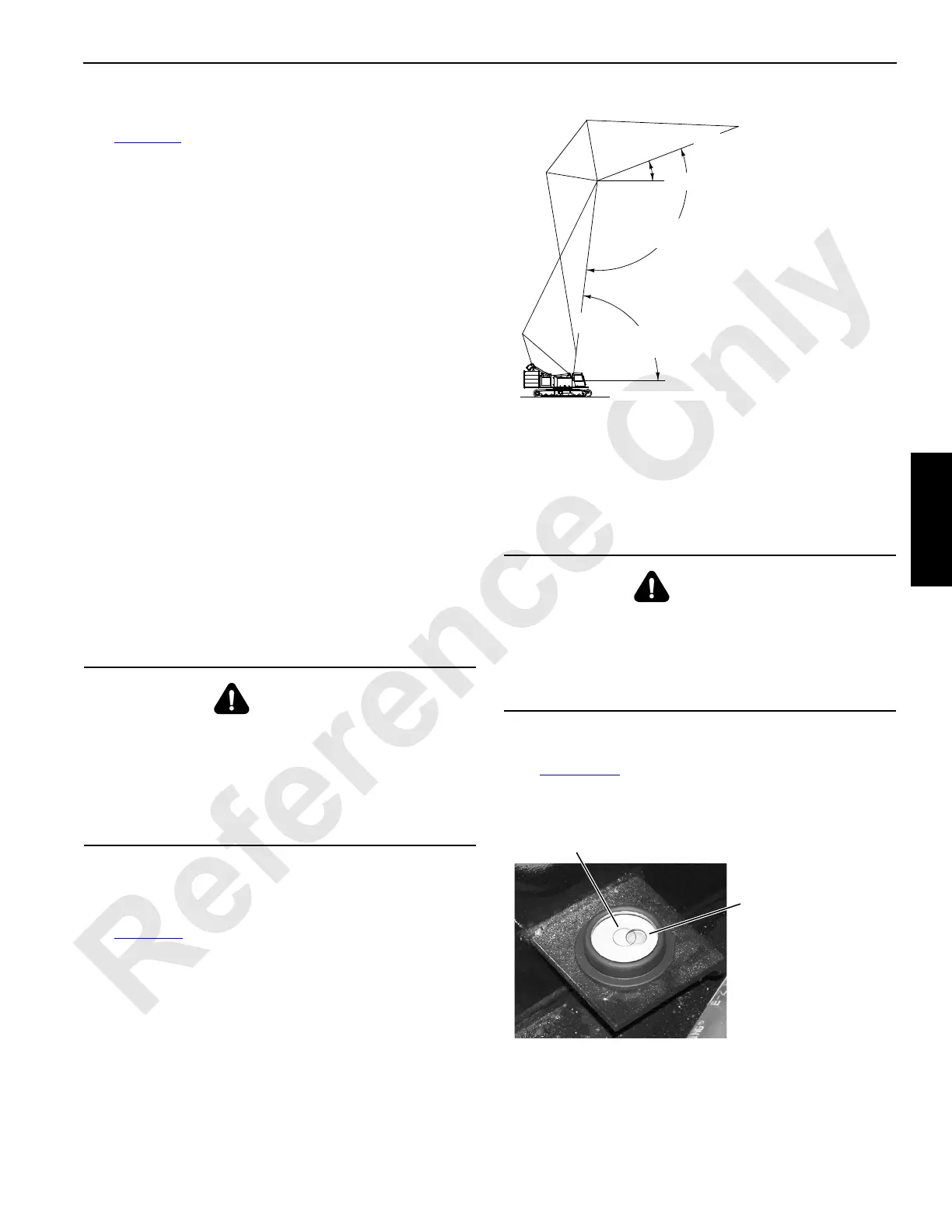
C9. Upperworks Level
Indicates crane levelness from front to rear and from side to
side. The level is mounted on the left-front side of the rotating
bed (Figure 3-10
). The crane is level when the bubble is
centered in the circle. The crane is one degree out of level
when the bubble is touching the outside edge of the circle.
WARNING
Overload Hazard!
Use boom angle indicator only as a guide to position
boom near angle corresponding to radius for given load.
In all cases, radius shall govern capacity. Exceeding
radius given in capacity chart can result in tipping or
structural damage.
WARNING
Tipping Hazard!
Unless otherwise specified on capacity chart, all crane
operations must be performed with crane level to within
one percent of grade in all directions – 1 ft in 100 ft (0,3 m
in 30 m); otherwise, crane could tip.
FIGURE 3-9
A886
Boom
Angle
Jib
Angle
Horizontal
Boom to
Jib Angle
Horizontal
C
L
C
L
Boom
Jib
FIGURE 3-10
P2361
Bubble — Shown
Approximately One-Half
Degree Out of Level
Circle