Manitowoc Published 03-29-17, Control # 064-23 v2 4-95
14000 OPERATOR MANUAL SETUP AND INSTALLATION
Install Jib Stop
1. Remove pins (3, View A, Figure 4-41), and lower jib stop
assembly (1) to working position on boom top (4).
See Figure 4-44
for the remaining steps.
2. Pin jib stop (1, View A) to lugs on boom top (4).
3. Store pins (3, View C).
4. Adjust jib stop length as follows (View A):
a. Remove offset pins (6).
b. Adjust position of inner tubes (7) so holes in tubes
are aligned with proper offset holes in links (8).
c. Reinstall offset pins (6).
5. Connect jib stop control cable as follows:
a. Route cable extension (9, stored in jib butt) through
sheave (10) in boom top (View A).
b. Connect end of cable extension (9) to jib stop
control cable (11) with shackle (12, View A).
c. Connect other end of cable extension (9) to winch
control cable (13) with shackle (12, View F).
6. Use winch (14) on jib top to take load off safety pins (16,
View B) (loosen pins) and remove safety pins.
7. Pay out control cable to engage jib stop pins (17, View
C). Then pay out an additional 2 ft (0,6 m) of control
cable.
8. Store safety pins (16, View C).
9. Boom up until jib point just clears ground.
Install Load Line
See Load Line Reeving instructions on Page 107 for proper
routing and reeving of load lines.
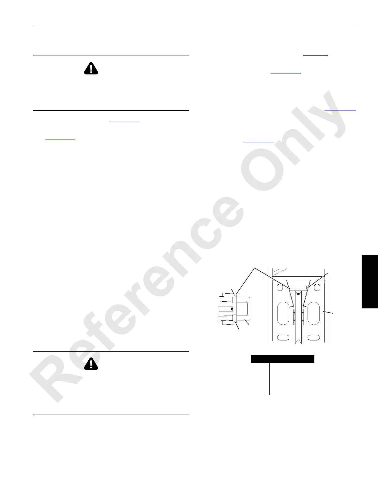
Remove the rope guards (Figure 4-45
) to pull the load line
through the jib point and strut without removing the socket
and wedge.
Install Block-Up Limit Control and Connect Jib Wiring
Install block-up limit components as shown in Figure 4-38
and in Boom Wiring and Limits Electrical Drawing at end of
this section.
Connect plugs from electric cables to corresponding
receptacles (see Figure 4-39
).
• To prevent dirt and moisture from entering electric
components, connect dust caps (1) to all unused plugs,
terminating plugs, and receptacles.
• Connect terminating plugs (SP) to unused plugs. Failing
to perform this step will cause a fault alert and
corresponding function will not operate properly.
• Install wind speed indicator assembly if removed for
shipping. Use star washers to attach mounting bracket
to jib top to provide a good ground (see Wind Speed
Assembly drawing at end of this section).
Connect electrical cable at base of wind speed mounting
bracket.
WARNING
Crushing Injury!
Jib stop pins are spring engaged. Do not remove safety
pins until jib stop assembly is pinned in working position
and control cables are attached and tensioned.
WARNING
Falling Jib Hazard!
Visually observe that jib stop pins fully engage holes in jib
stop frame as boom and jib are raised from ground.
Jib can be pulled over backwards if jib stop pins do not
engage.
FIGURE 4-45
Item Description
1Jib Top
2Jib Strut
3 Rope Guard
4 Safety Pin
4
1
4
2
3
14COM4171
4