Manitowoc Published 03-29-17, Control # 064-23 v2 4-3
14000 OPERATOR MANUAL SETUP AND INSTALLATION
SELF-ERECTING EQUIPMENT
The 14000 is equipped with the following self-erect
components for assembly and disassembly (see Figure 4-1
):
• Carbody jacks with pads for lifting the crane onto and off
a trailer. The jacks are controlled by handles on front of
the carbody.
• Hydraulically actuated pins for connecting and
disconnecting the crawlers to and from the carbody. The
pins are controlled by handles on front of the carbody.
• Hydraulic cylinders for raising and lowering the gantry.
The cylinders are controlled by switches on a remote
control.
• Hydraulically actuated pins for engaging and
disengaging the gantry backhitch pins. The pins are
controlled by switches on a remote control.
• Hydraulically actuated mast arms for raising the mast to
the operating position and lowering it to the transport
position. The arms are controlled by a switch on the
overhead console in the operator’s cab.
• Mast which can be used as a boom to handle the crane’s
crawlers and counterweights and to assemble and
disassemble the boom and jib. The mast is controlled by
the boom hoist control handle in the operator’s cab
• Hydraulically actuated pins for connecting the boom butt
to the rotating bed. The pins are controlled by a switch
on the overhead console in the operator’s cab.
• Assembly block — 30 USt (27 t) — and 4-leg chain sling
with hooks for handling components
ASSEMBLY AND DISASSEMBLY NOTES
The crane, boom, and jib shall be assembled and
disassembled by experienced personnel trained in erection
and operation of construction cranes.
Before attempting to assemble, operate, or disassemble the
crane, read and become thoroughly familiar with the
instructions in this section and in the boom and jib assembly
drawings at end of this section.
Contact your Manitowoc dealer for assistance if any
procedure is not fully understood.
ASSEMBLY AND DISASSEMBLY AREA
Select an assembly/disassembly area that has a firm, level,
uniformly supporting surface. Make sure the area is large
enough to accommodate the crane and the selected boom
length, movement of trucks with trailers, and movement of an
assist crane (if used).
Set the jack pads on a flat, firm foundation that will support
the load placed on them. See Table 4-1
for loadings.
Do not set the jack pads in holes, on rocky ground, or on
extremely soft ground. Jack pads could break.
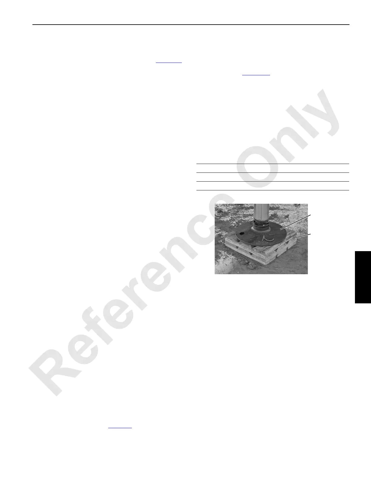
If necessary, use wood blocking or steel plates under the
jack pads to properly distribute loading and to provide a
smooth surface (Figure 4-2
). The wood blocking or steel
plates must be:
• Free of defects
• Strong enough to prevent being crushed or bent
• Of sufficient length and width to prevent settling under
load
Contact your Manitowoc dealer for ground bearing
information.
Table 4-1
Load Data for Carbody Jacks
ACCESSING PARTS
Some parts of the crane, boom, and jib cannot be reached
from the ground. Take necessary precautions to prevent
slipping and/or falling off the crane or boom during assembly
disassembly, maintenance, or other work. Falling from any
height could result in serious injury or death.
Owner/user must provide workers with approved ladders or
aerial work platforms to access those areas of the crane,
mast, boom, and jib that cannot be reached from ground or
from steps, ladders, catwalks, and platforms provided by
Manitowoc.
Adhere to local, state, and federal regulations for handling
personnel and for personnel fall protection.
Do not use top of mast, boom inserts, and boom top as
walkways.
Catwalks and platforms are provided on the boom butt for
accessing the boom butt wire rope guide.
Maximum Load on each Jack — 72,000 (32 659 kg)
Jack Pad Diameter —24 in (610 mm)
Jack Pad Weight — 50 lb (23 kg)
Jack Pad
Blocking
P2474
FIGURE 4-2