SETUP AND INSTALLATION 14000 OPERATOR MANUAL
4-78
Published 03-29-17, Control # 064-23 v2
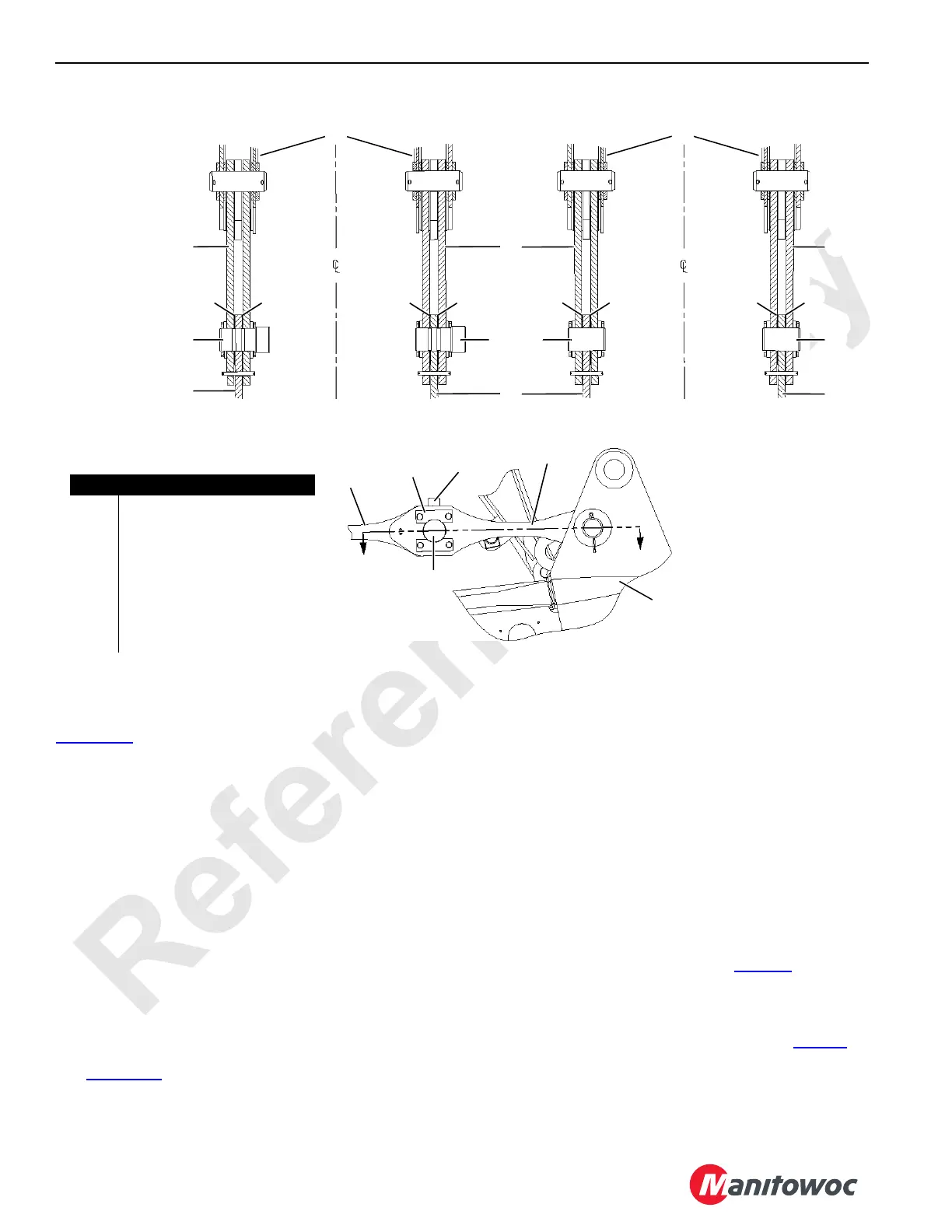
Replace Load Pins for Duty-Cycle Operation
If desired for duty-cycle operation only, load pins (4,
Figure 4-36
) in boom top (1) can be replaced with standard
pins (5).
NOTE: If standard pins are used, the load pins in RCLl/RLI
must be turned OFF in the operator’s cab to
prevent error codes from being displayed (see
Folio 2128, Manitowoc Model 14000 Rated
Capactiy Limiter (RCL) / Rated Capacity Indicator
(RCI) Manual, for instructions.
The load pins must be reinstalled for liftcrane operation.
Whenever load pins are reinstalled, the pins must be
recalibrated as instructed in Folio 2128, Manitowoc
Model 14000 Rated Capactiy Limiter (RCL) / Rated
Capacity Indicator (RCI) Manual.
To prevent side play of links (2) one shim (6) must be
installed on each side of straps (3).
Raise Boom Top Wire Rope Guide
See Figure 4-37 for the following procedure.
1. Attach lifting slings to wire rope guide (1 View A).
2. Hoist until slings are just tight and remove pins (2).
3. Raise wire rope guide to working position (View B).
4. Remove pins (3, View B) securing struts (4) in stored
position.
5. Pin struts (4, View B) to boom top and store pins (3) in
wire rope guide frame.
Remove Lower Boom Point Sheaves
Depending on boom length (and luffing jib length if installed)
it may be necessary to remove lower boom point sheaves.
See Liftcrane Capacity Chart or Luffing Jib Raising
Procedure to determine boom and jib raising limitations. See
Lower Boom Point Assembly topic on Page 89
for sheave
removal instructions.
Install Jib
If required, install jib. See Jib Installation topic on Page 91 for
instructions.
Item Description
1 Boom Top
2Links
3Strap
4 Load Pin
5Pin
6 Shim (4 each)
7 Keeper Plate with Cap Screws
and Lock Washer
A
FIGURE 4-36
Section A-A
With Load Pins
2
3
2
Section A-A
Without Load Pins
A
1
6
4 or 5
7
2 2
3
3
3
4 4 5 5
1
1
66
66
66
66

 Loading...


