Manitowoc Published 03-29-17, Control # 064-23 v2 4-97
14000 OPERATOR MANUAL SETUP AND INSTALLATION
4. Store backstay spreader (6) and links (3).
Remove Jib Sections
Reverse installation steps to remove jib sections.
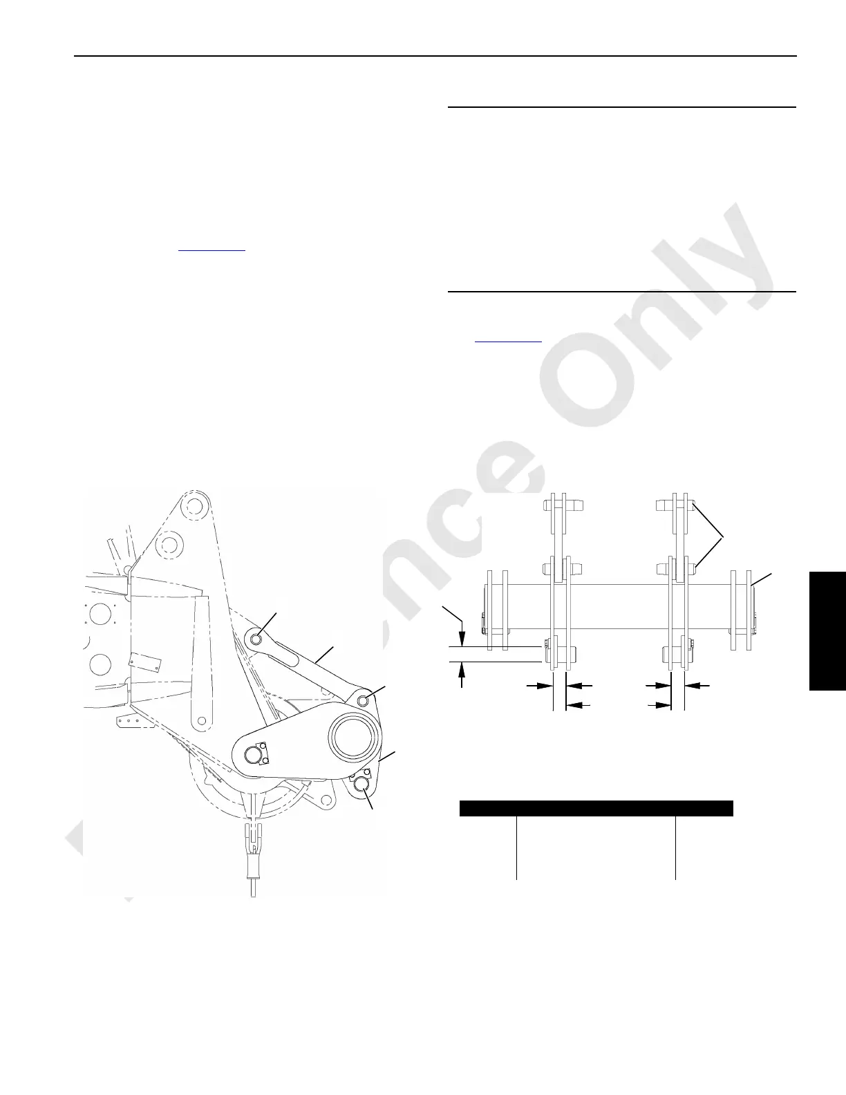
Pile Driver Adapter Installation
Installation
If required, install the optional pile driver adapter to the boom
point as shown in Figure 4-46
.
Operating Specifications With #76 Top
See Figure 4-46 for the installation.
• Maximum Boom Length = 134.5 ft (42.7 m)
• Maximum Load Per Side = Design Load divided by 2
• Design Loads = 60,000 lbs at 65° Boom Angle and
48,000 lbs at 55° Boom Angle
CAUTION
Pile driver adapter shall be used only with freely
suspended loads.
Any side load or torque generated by owner supplied
attachments will reduce design loads given in this section.
In such cases, contact your Manitowoc dealer for
specifications which meet your particular application.
Values given in this publication apply to pile driver adapter
only. In all cases, pile drive adapter loads cannot exceed
those listed for main boom capacity.
23.78 in
604,0 mm
2.87 in
73,0 mm
Item Identification Qty.
1 Adapter (MCC 81000908) 1
2 Boom Joint Pins 4
3 Pin with Keeper Plate 2
4Links 2
End View
All Linear Dimensions
± 0.060 in (1,524 mm)
2.87 in
73,0 mm
Pin Hole
3.00 in
76,2 mm
2
2
3
1
3
FIGURE 4-46
1
81000908b
81000908a
4
2

 Loading...


