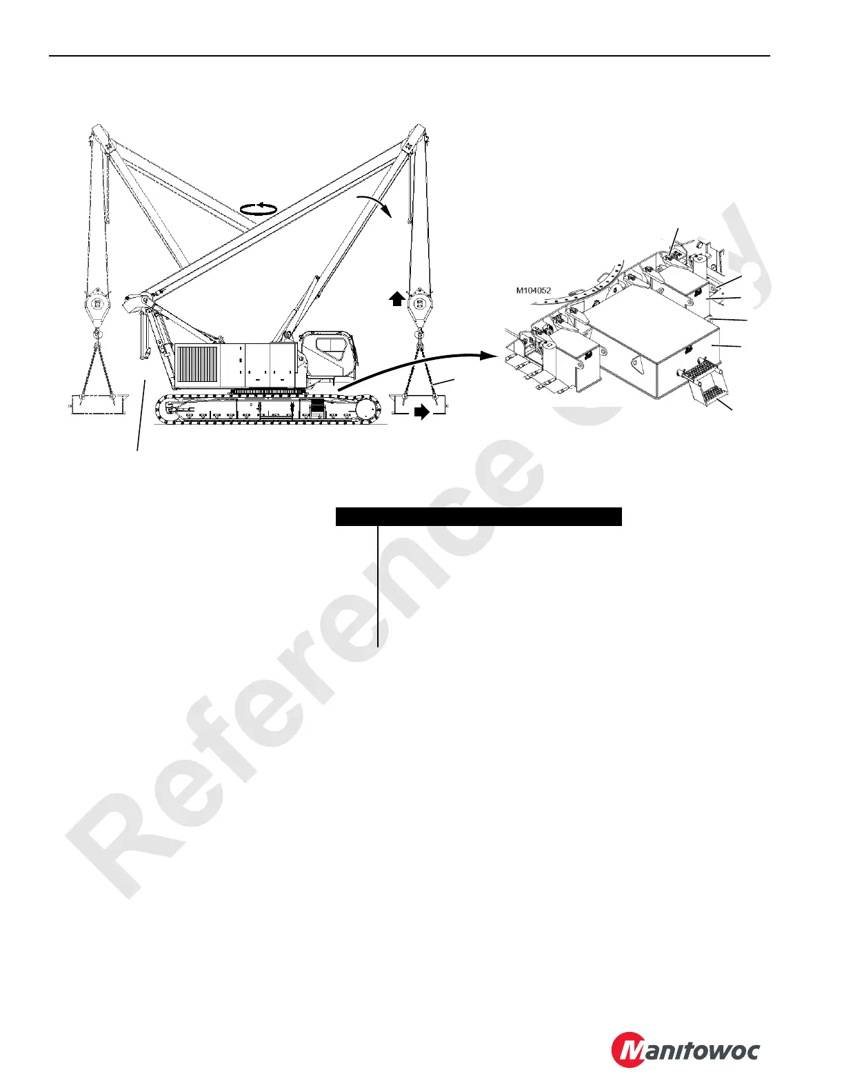
Home
Manitowoc
Construction Equipment
14000
Manitowoc 14000 User Manual
5
of 1
of 1 rating
270 pages
Give review
Manual
Specs
To Next Page
To Next Page
To Previous Page
To Previous Page
Loading...
Reference
Only
SETUP AND INST
ALLATION
14000 OPERA
T
OR MANUAL
4-56
Published 03-29-17, Control # 064-23 v2
Vie
w A
FIGURE
4-25
Item
Description
1
Pin with Hair-Pin
Cotters (2 each box)
2C
h
a
i
n
S
l
i
n
g
3
Lifting Lu
g
4
Carbody Counterweight (center)
5
Carbody Counterweight (side,
Series 3 only)
6
S
tep with Quick-Release Pins
47 lb (21 kg)
2
3
5
1
14COM4190a
3
4
6
Vie
w B
Remove crane counte
rweight befo
re
removing carbody counterweights.
193
195
Table of Contents
Default Chapter
5
Table of Contents
5
Section 1
13
Crane Data
13
Crane Weights
13
Crane/Attachment Identification
13
Reference to Past and Current Production in this Manual
13
Change of Ownership Registration
13
Manitowoc Dealer
13
Crane Orientation
13
Identification and Location of Components
14
Outline Dimensions
17
English and Metric Conversions
19
Direct Conversion
19
Inverse Conversion
19
Section 2
21
Continuous Innovation
23
Nameplates and Decals
23
Safety Messages
23
General
23
Safety Alert Symbol
23
Signal Words
23
Symbol Identification
23
Safety and Information Signs
25
Maintaining Signs
25
Ordering Signs
25
Crane Access Points
27
General
27
Getting on or off Crane
27
Operator Manual/Capacity Chart Storage
28
General
28
Storing Manuals
28
Deploying Swing Radius Barrier
29
Storing Swing Radius Barrier
29
Safe Operating Practices
30
General
30
Read Operator Manual
30
Operator Qualifications
30
Operator Conduct
30
Handling Load
32
Size of Load
32
Attaching Load
32
Lifting/Moving Load
33
Multiple Load Line Operation
34
Signals
35
Holding Load
35
Safety Devices
36
Operational Aids
36
Category 1 Operational Aids
36
Category 2 Operational Aids
37
Assembling, Disassembling, or Operating Crane Near Electric Power and Transmission Lines
38
Electrocution Hazard
38
Set-Up and Operation
38
Electrocution Hazard Devices
39
Electrical Contact
39
Refueling
40
Fire Extinguishers
40
Accidents
40
Safe Maintenance
40
Maintenance Instructions
40
Safe Maintenance Practices
40
Environmental Protection
42
Boom Disassembly Safety
45
General
45
Location
45
Pin Removal
45
Disassembly Precaution
45
Personnel Handling Policy
46
Pedestal/Barge Mounted Cranes
48
Pedestal Mounted Crane
48
Barge Mounted Crane
48
Definition
48
Examples
48
Capacity Charts
50
Shock Loading
50
Operation on Barge
50
Definition
50
General
50
Definitions
50
Crane Inspection
51
Transporting Crane on Barge
51
Section 3
53
Standard Hand Signals for Controlling Crane Operations
58
Symbol Identification
60
Cab Window Operation
66
Opening Windows for Ventilation
66
Exiting Cab in Emergency
66
Operating Controls
66
General
66
Past Production Cab
66
Current Production Cab
66
Past Production Cab Only
66
Current Production Cab Only
66
Controls Identification and Function
70
A - Engine Controls
70
A1. Engine Ignition Switch
70
A2. Engine Emergency Stop Switch
70
A3. Engine Hand Throttle
70
A4. Engine Foot Throttle
70
A5. Engine Clutch Lever
70
A6. Battery Disconnect Switch
71
A7. DPF Switch
71
B - Accessory Controls
74
B1. Overhead Windshield Wiper Switch
74
B2. Front Windshield Wiper-Washer Switch
74
B3. Climate Control Panel
74
B4. Crane Work Lights Switch
74
B5. Panel Light Switch
74
B6. Boom Pins Switch
75
B8. Dome Light Switch
75
B9. Overhead Fan Switch
75
B10. Horn Switch
75
B11. Cab Tilt Switch
75
B12A. Cigarette Lighter Receptacle
75
B12B. Power Supply Receptacle
75
B13. Programmable Receptacle
75
B14. Fire Extinguisher
75
B15. Radio/CD Player (Optional)
75
C - Indicators
77
C1. Fuel Level
77
C2. Engine Coolant Temperature
77
C3. Engine Oil Pressure
77
C4. Battery Voltage
77
C5. Drum Rotation Indicators
77
C6. Rear View Mirrors
77
C7. Boom Angle Indicator
77
C8. Cab Beacon (Optional)
77
C9. Upperworks Level
77
D - Special Controls
78
C10. Wind Speed Transmitter
78
D1. Rated Capacity Indicator/Limiter Display and Indicator Lights
78
D2. Main Display
78
D3. Display Touch Pad Controls
78
D4. Limit Bypass Switch
78
D5. Luffing Jib Limit Bypass Switch
78
D6. Seat Switch
78
E - Boom Hoist Controls
82
E1. Drum 4 (Boom Hoist) Park Switch
82
E2. Drum 4 (Boom Hoist) Handle
82
F - Load Drum Controls
83
F1. Drum 1 (Front Drum) Park Switch
83
F2. Drum 2 (Rear Drum) Park Switch
83
F3. Drum 3 (Auxiliary/Luffing Jib) Park Switch
83
F4. Drum 1 (Front Drum) Handle
83
F5. Drum 2 (Rear Drum) Handle
83
F6. Drum 3/4 (Auxiliary/Luffing Jib) Handle
83
F7. Drum 1 (Front Drum) Working Brake Pedal
83
F8. Drum 2 (Rear Drum) Working Brake Pedal
83
G - Swing Controls
84
G1. Swing Park Switch
84
G2. Swing Handle
84
G3. Swing Holding Brake Switch
84
H - Travel Controls
85
H1. Travel Park Switch
85
H2. Travel Speed Selector
85
H3. Travel Cruise Selector
85
Limit Devices
86
Boom Maximum up Limit
86
Boom down Limit
86
Block-Up Limit
86
H4. Left Crawler Handle or Pedal
86
H5. Right Crawler Handle or Pedal
86
Luffing Jib up Limit
87
Luffing Jib down Limit
87
Maximum Bail Limit
88
Minimum Bail Limit
88
Seat Controls
88
Preparing Crane for Operation
89
Operation
89
Engine Startup
89
Boom Hoist Operation
92
Luffing Hoist Operation
93
Swing Operation
94
Load Drum Operation
95
Liftcrane Operation - (with Free Fall Off)
95
Liftcrane Operation - Free Fall
95
Clamshell Operation
97
Travel Operation
98
Luffing Jib Setup Mode
100
Stopping Engine/ Leaving Crane Unattended
101
Remote Controls
101
General
101
Set-Up Remote Control
101
Power Switch
102
Stop Switch
102
Gantry Cylinders
102
Back Hitch Pins
102
Manual Controlled Handles
103
Crawler Pin Controls
103
Carbody Jack Controls
103
Displays
104
Display Controls
104
Display Brightness and Color Contrast
104
Factory Default Display Settings
104
Blank Display
104
Rated Capacity Indicator/Limiter Display
104
Main Display
104
Display Touch Pad Controls
104
Display Select Buttons
104
Select Buttons
104
Main GUI Display Format
105
Screen Prompts
105
Menu Screen
106
Information Screen
106
Boom to Luffing Jib Working Angle
106
Wind Speed Indicator
106
Mast Angle
106
Hydraulic Tank
107
Battery
107
Engine (All)
107
Crane Faults
107
Tier 4 Engine Fault
107
Diagnostic Screens
110
Diagnostic Screen Component Icons
110
Tier 4 Engine Diagnostic Information
111
Drum Diagnostic Screens
111
Swing Diagnostic Screen
112
Travel Diagnostic Screen
112
Function Mode Screens
113
Accessory Diagnostic Screen
113
Drum Functions
114
Swing Functions
114
Remote Control Functions
114
Multiple Points or Load Pin Disable Functions
114
Swing or Track Speed Limits
114
Drum Functions
115
Swing Torque
115
Boom or Swing Motion Limiter Mode
116
Remote Control
116
Multiple Points or Load Pin Disable Functions
116
Fan Function
116
CAN Bus Diagnostic Screen
118
Packet Information
118
Digital Output Disable Fault
118
Engine Node Status
118
Crane Status
118
Camera Screen (Optional)
124
Pressure Test and Calibration Screen
124
Pressure Sender Test
124
Control Calibration
125
High Pressure Test
125
Charge Pressure Test
126
Wind Conditions
127
Preparation for Cold Weather
129
Crane Limitations
129
Wire Rope
129
Cold Weather Starting Aid
129
Cooling System
129
Batteries
129
Engine Oil
129
Fuel Oil
129
Gear Oil
129
Coolant and Oil Pan Heaters
129
Hydraulic Oil
130
General
130
Cold Weather Heater Package
131
General
131
Heaters
131
Turning Heaters on
131
Turning Heaters off
131
Circuit Breakers
131
Cold Weather Package - Past
132
Cold Weather Package - Current
133
Boom and Jib Assembly Drawings
139
Liftcrane Mast Capacities
139
Optional Attachments
139
General Safety
139
Crane Orientation
139
Self-Erecting Equipment
141
Assembly and Disassembly Notes
141
Assembly and Disassembly Area
141
Accessing Parts
141
Crane Weights
142
Handling Components
142
Retaining Connecting Pins
142
Cold Weather Mast Operation
143
Shipping Crane Components
143
Operating Controls
144
Pre-Start Checks
144
Engine
144
Gear Boxes
144
Hydraulic System
144
Electric System
144
Shipping Data
145
Crane Assembly
151
Remove Protective Covers from Cab Windows
151
Remove Crane from Trailer
153
Deploy Operator's Cab
155
Raise Mast to Operating Position
155
General
155
Raising Procedure
157
Install Assembly Block
161
Install Crawlers
163
Deploy Crawler Steps
167
Install Platforms
167
Assemble Boom and Jib
167
Install Counterweight
169
Assemble Crane Counterweight
169
Install Carbody Counterweight
169
Install Crane Counterweight
171
Install Boom Butt
175
Lifting Boom Butt
175
Connect Boom Butt to Crane
177
Raise Boom Butt Wire Rope Guide
177
Remove Assembly Block
179
Connect Boom Butt to Boom
179
Section 4
139
Pre-Raising Checks
182
Crane Disassembly
182
Lower Boom and Jib to Ground
182
Disconnect Boom Butt from Boom
185
Remove Boom Butt
189
Remove Counterweight
191
Remove Crane Counterweight
191
Disassemble Jib and Boom
195
Remove Platforms
195
Remove Carbody Counterweights
195
Disassemble Crane Counterweight
195
Remove Crawlers
197
Remove Assembly Block
201
Lower Mast to Transport Position
201
Install Protective Covers on Cab Windows
203
Store Operator's Cab
203
Install Crane on Trailer
205
Boom Ladder
206
General
206
Removing Ladders from Storage
206
Using Ladders
207
Storing Ladders
207
Boom and Jib Rigging
207
Assist Crane Requirements
207
Blocked Crawlers
207
Handling Components
208
Assembly Drawings
208
Identifying Boom and Jib Components
209
Boom Installation - #76
213
General
213
Raise Auxiliary Drum Wire Rope Guide
213
Install Upper Boom Point
213
Connect Boom Straps
213
Install Intermediate Suspension
215
Replace Load Pins for Duty-Cycle Operation
216
Raise Boom Top Wire Rope Guide
216
Remove Lower Boom Point Sheaves
216
Install Jib
216
Install Pile Driver Adapter
217
Install Clamshell Wire Rope Guide
217
Connect Boom Butt to Boom
217
Install Load Line
217
Install Block-Up Limit Control and Connect Boom Wiring
219
Boom Removal
223
Lower Boom and Jib to Ground
223
Store Load Lines
223
Remove Block-Up Limit Control and Disconnect Boom Wiring
223
Disconnect Boom Butt from Boom
223
Disassemble Boom Sections
223
Lower Boom Point Assembly
227
General
227
Removing and Installing Sheave Clusters
227
Greasing Sheave Bearings
227
Adjusting Bearing Side Play
227
Jib Installation - #134
229
General
229
Prepare Boom
229
Install Butt
229
Install Inserts
229
Install Top
229
Install Jib Pendants
231
Install Backstay Pendants
231
Install Jib Offset Links or Pendants
231
Connect Jib Backstay Pendants
231
Install Jib Stop
233
Install Load Line
233
Install Block-Up Limit Control and Connect Jib Wiring
233
Jib Removal - #134
234
Lower Boom and Jib
234
Store Jib Stop
234
Lower Strut
234
Remove Backstay Pendants
234
Remove Jib Pendants
234
Pile Driver Adapter Installation
235
Remove Jib Sections
235
Installation
235
Operating Specifications with #76 Top
235
Wire Rope Installation
236
Wire Rope Storage
236
Removing Wire Rope from Shipping Reel
236
Seizing and Cutting Wire Rope
236
Anchoring Wire Rope to Drum
237
Winding Wire Rope Onto Drum
239
Anchoring Wire Rope to Socket and Wedge
240
Anchoring Wire Rope to Button Socket
242
Breaking in Wire Rope
242
Pad Eye Usage for Wire Rope Reeving
242
General
242
Safety
242
Load Line Reeving
245
Wire Rope Specifications
245
Wire Rope Installation
245
Liftcrane
245
Reeving Diagrams
245
Dead-End Locations - Lower Boom Point
245
Guide Sheave Identification
245
Load Blocks
245
Load Block Tieback
257
General
257
Specifications
257
Boom Hoist Reeving
257
Wire Rope Installation
257
Shackle
257
Sling Length
257
Sling Capacity
257
Section 5
259
Lubrication
259
Lube and Coolant Product Guide
261
Section 6
265
Inspection and Maintenance Checklist
265
Fiberglass Maintenance
265
Other manuals for Manitowoc 14000
Service And Maintenance Manual
286 pages
Service Maintenance Manual
278 pages
Product Guide
36 pages
5
Based on 1 rating
Ask a question
Give review
Questions and Answers:
Need help?
Do you have a question about the Manitowoc 14000 and is the answer not in the manual?
Ask a question
Manitowoc 14000 Specifications
General
Brand
Manitowoc
Model
14000
Category
Construction Equipment
Language
English
Related product manuals
Manitowoc 1400A
164 pages
Manitowoc 14000 1 Series
6 pages
Manitowoc 14000 2 Series
4 pages
Manitowoc 16000
292 pages
Manitowoc 18000
302 pages
Manitowoc 12000-1
10 pages
Manitowoc MLC100-1
218 pages
Manitowoc MLC165-1
256 pages
Manitowoc 16000 Series 2
2 pages
Manitowoc Grove GMK 5200-1
346 pages
Manitowoc Grove GMK4100L-1
1016 pages
National Crane NBT40-1 Series
206 pages