BOOM 18000 SERVICE/MAINTENANCE MANUAL
4-8
Published 12-05-17, Control # 035-23
3. Connect wires from potentiometer to proper terminals on
terminal strip.
4. Make sure all parts are securely fastened to their
mounting position.
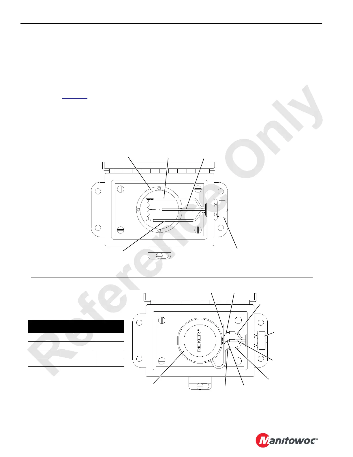
Solid State Sensor
When replacing existing pendulum-type potentiometer with
current production solid state sensor, take the following
precautions (see Figure 4-7
, View B):
1. Identify all input wires to existing potentiometer.
2. Cut existing input wires near terminal strip (if used) to
allow for splicing.
3. Remove existing potentiometer and terminal strip (if
used).
4. Mount new sensor in existing holes as shown in View B.
5. Refer to wiring chart in View B and parallel splice sensor
wires to existing input wires with crimp, solder, and heat
shrink tubing.
6. Seal green wire on sensor with heat shrink tubing and
coil up.
(-)
(+)
1
2
3
NOTE: Current through potentiometer
must not exceed 10 milliamperes.
120° Pendulum-Type
Potentiometer
Black (Pin #2)
(Ground Bus)
White (Pin #3)
(5V DC System Bus)
Green (Pin #1)
(Mast Angle)
3-Pole Receptacle
with Protective Cap
0 - Black
(Pin #2)
87FA - White
(Pin #3)
88MA Green
(Pin #1)
3-Pole Receptacle
with Protective Cap
Solid State Sensor (+/-100°)
M.C.C. #A13335
Vendor #CS17
Input Wires
From
Sensor
Wires To
Operation
Code
Black Black Ground
Green Green Signal
White Red 10 Volts DC
White N/C
VIEW B
VIEW A
Black
Green
White
Red
Position Sensor
Like This
FIGURE 4-7
18CSM4-105
18CSM4-106
 Loading...


