5-48 Published 7-23-2020, Control # 668-02
SET-UP AND INSTALLATION GRT9165 OPERATOR MANUAL
Front Mounting Pin Handle
The front mounting pin handle (5, Figure 5-31) moves in
unison with the front mounting pin (3), providing a visual cue
for operators outside of the operator cab know status of the
front boom extension mounting pin (3):
• Handle up—The front mounting pin is extended in the
front mounting bracket and the boom extension
installation pins are unlocked.
• Handle down—The front mounting pin is retracted and
the installation pins are locked.
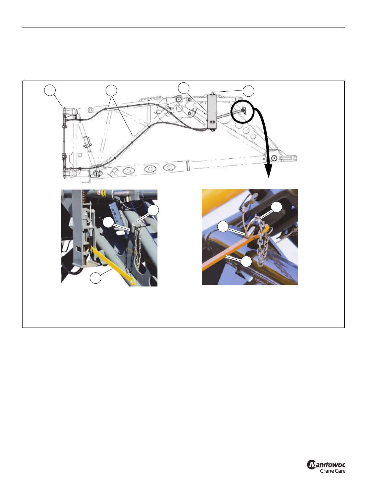
Boom Extension Mounting Brackets
NOTE: The fly section and boom extension base section
must be connected with the fly section in the
stowed position to secure the boom extension to
the side of the boom.
The main boom base section features the following mounting
brackets for stowing the fly section and boom extension base
section:
• Rear Boom Extension Mounting Bracket—Located
nearest to the superstructure cab is the rear boom
extension mounting bracket (1, Figure 5-32). The boom
extension base section is pinned to the fly section. The
fly section is secured to the side of the boom base
section with the electrically actuated pin.
• Front Boom Extension Mounting Bracket—Located
nearest the boom nose is the front boom extension
mounting bracket (6, Figure 5-32). The front mounting
bracket pin is actuated with the boom extension
actuating mechanism. For more information, see Boom
Extension Pin Interlock Mechanism, page 5-47.
• Front Fly Section Mounting Bracket—Located near the
lift cylinder pin. The front fly section bracket (9,
Figure 5-32) secures the fly section the main boom.
Stow Boom Extension
Front Boom Extension Pin Extended
Boom Extension Installation Pins Unlocked
Deploy Boom Extension
Front Boom Extension Pin Retracted
Boom Extension Installation Pins Locked
5
5
7
6
2
FIGURE 5-31
1
3
4
9967
9968
9969
6
7

 Loading...


