5-30 Published 7-23-2020, Control # 668-02
SET-UP AND INSTALLATION GRT9165 OPERATOR MANUAL
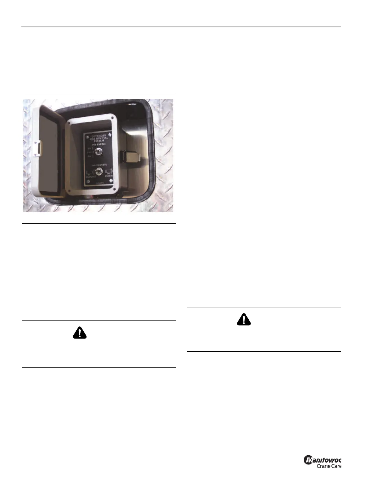
6. Using the appropriate outrigger box removal control (on
the left front fender for the front outrigger box, on the
right rear fender for the rear outrigger box, or the remote
control), hold the Pin Enable switch to the ON position
(Figure 5-18) and push the Pin Control switch to
DISENGAGE until the pinning cylinder rods are fully
retracted.
7. Disconnect the carrier external electrical connector from
the outrigger electrical connector (7, Figure 5-19).
8. Disconnect the carrier hydraulic quick disconnects from
the outrigger hydraulic connectors (8). Stow the carrier
hydraulic lines on stowage bracket (2, Figure 5-17).
9. Lift the outrigger box (6) from the carrier.
10. Stow the quick release pins (2) in the stowage clamps
(1) on the outrigger box.
11. Stow the electrical connector (7) in the plug provided on
the fender.
12. Lower the outrigger box on to a suitable surface.
Outrigger Box Installation
NOTE: The outrigger box assembly weighs approximately
9427 lb (4276 kg).
NOTE: The outrigger boxes must be installed in the correct
locations. The outrigger boxes are marked Front
(install on single axle end) and Rear (installed on
the tandem axle end).
1. Program the RCL for On Rubber 360° rotation load
chart. For more information, see Enter Rigging Code,
page 4-159.
2. While the outrigger box is on a stable surface, relieve
pressure from outrigger box hydraulic hoses using bleed
fittings (9, Figure 5-19).
3. Make sure the outrigger pressure bleed valve (1,
Figure 5-17) is closed.
4. Apply grease to the upper outrigger box pin saddles on
the carrier frame (four places per end). For more
information, see the SECTION 6 - Maintenance and
Lubrication.
5. Connect sling assembly to the lifting lugs (4,
Figure 5-19) provided on the outrigger box.
6. Lift the outrigger box into position using the crane boom,
then lower the outrigger box assembly until the upper
pins on the outrigger box assembly are seated in the
saddles on the carrier frame.
7. Connect the carrier external electrical connector to the
outrigger electrical connector (7).
8. Install the carrier hydraulic quick disconnects to the
outrigger hydraulic connectors (8).
9. Lower the outrigger box aligning the pinning cylinder
pins (3) with the attach points on the carrier frame.
10. Using the appropriate remote mounted pin control box or
remote control, hold the Pin Enable switch at the ON
position and hold the Pin Control switch to the ENGAGE
position (Figure 5-18).
11. After the pinning cylinders have fully engaged the
outrigger box, install a quick release pin (2, Figure 5-19)
in the end of each of the cylinder rod ends (3).
DANGER!
Crush Hazard
Make sure the outrigger box is stable before removing the
rigging.
CAUTION!
Do not activate any switches on the control (Figure 5-18)
or remote control until you are thoroughly familiar with the
outrigger box installation and removal procedure.

 Loading...


