OPERATING PROCEDURES GRT9165 OPERATOR MANUAL
4-24 Published 7-23-2020, Control # 668-02
Stowing the Outrigger Mid-Extend Lock Pin
NOTE: If lock pin is wedged in outrigger beam hole, it may
be necessary to jog outrigger extend/retract switch
slightly while pulling upward on pin.
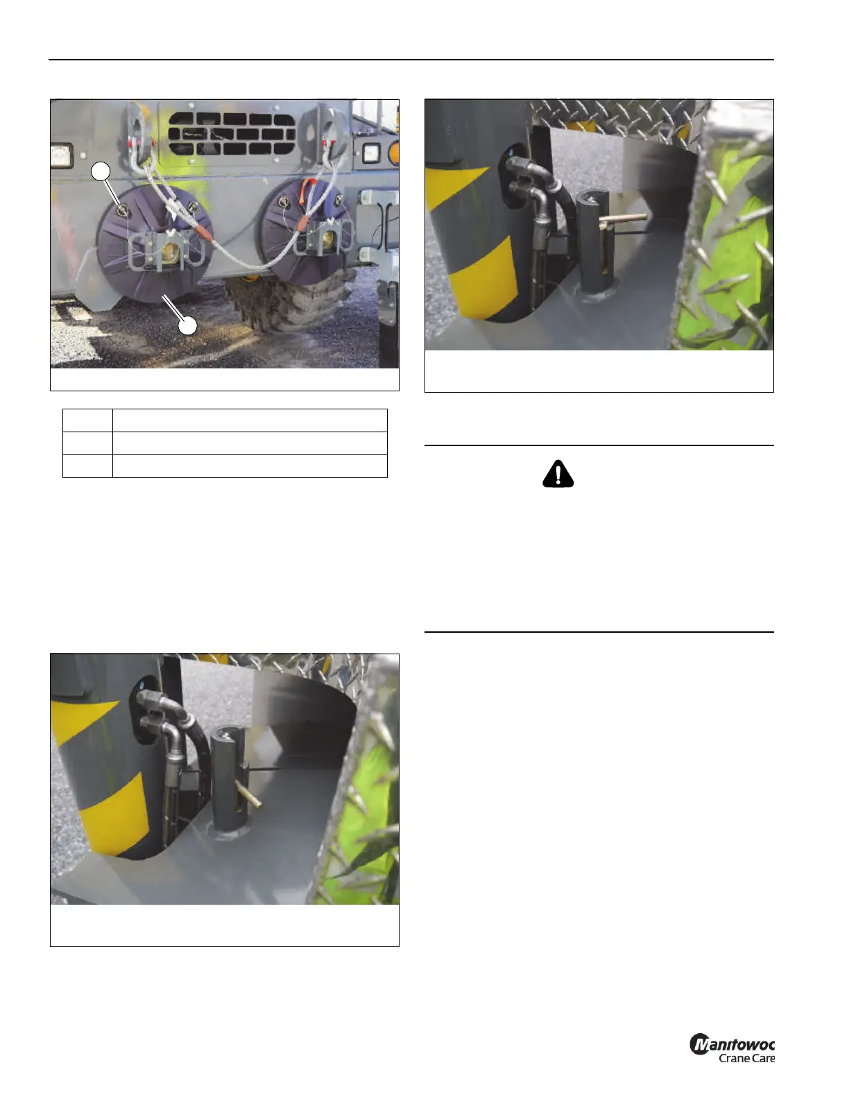
1. From its locked position (Figure 4-7), lift the locking pin
upward and turn 90° to the stowed position (Figure 4-8)
2. Continue to extend or retract the outrigger beam to the
desired position (fully retracted or fully extended).
Swinging the Boom and Superstructure
NOTE: The swing brake automatically disengages when
the swing controller is moved from the center
(neutral) position and it re-engages when the
controller is returned to the center position.
The Swing Brake Engaged Indicator
(8, Figure 3-14) on the Operator Display Module
(ODM) comes on (amber) when the swing brake is
engaged and goes off when the swing brake is
disengaged.
NOTE: Always operate controller with a slow, even
pressure.
NOTE: Swing Controller can be pushed through neutral
and toward opposite direction of swing to help slow
and stop the swing motion.
Item Description
1 Outrigger Pad Assembly
2 Quick Pin with Lanyard
9329-2
FIGURE 4-7
Mid-Extend Pin in Locked Position
DANGER
Crushing Hazard!
Death or serious injury could result from being crushed by
moving machinery. Before activating swing, sound the
horn and verify all personnel are clear of rotating and
moving parts.
Make sure the area around the boom, turntable and
counterweights are clear of all obstructions and personnel
before swinging.
9329-1
FIGURE 4-8
Mid-Extend Pin in Stowed Position

 Loading...


