Grove Published 11-22-2016, Control # 345-12 8-19
RT9130E-2 SERVICE MANUAL UNDERCARRIAGE
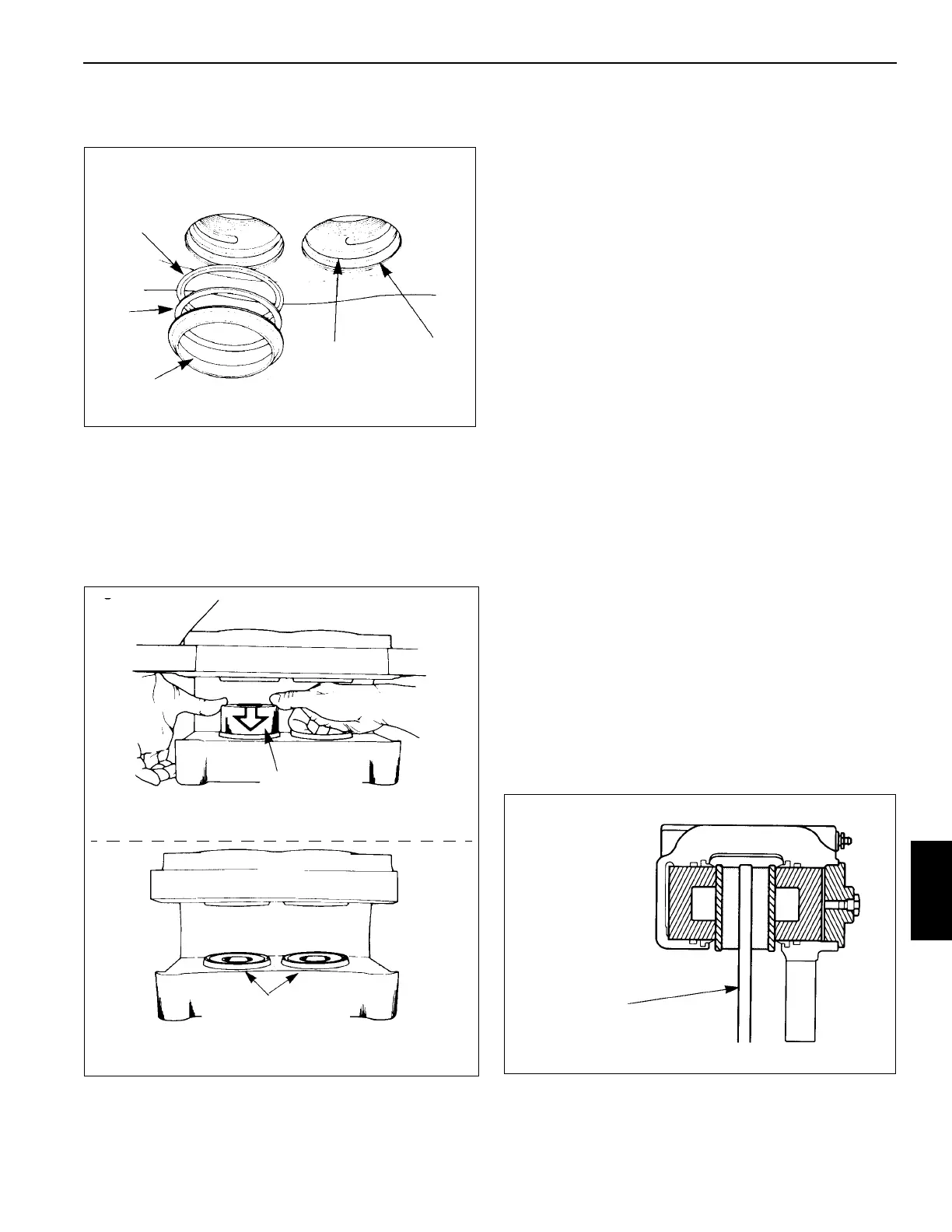
3. Install a new dust seal in the top groove of the bore
(Figure 8-16).
NOTE: Take care when you install the O-ring, so that the
cylinder cap threads do not cut the O-ring.
4. Install the pistons in the housing. Push the pistons in
from the lining side of the housing. Ensure the pistons
are straight in the bores. Push each piston into the bore
until the top of the piston is even with the top of the dust
seal (Figure 8-17).
5. Install a new O-ring in the groove of the cylinder cap.
Ensure the O-ring is not cut by the threads on the
cylinder cap.
NOTE: Apply extra grease on O-ring before installing
cylinder caps. this will keep O-ring from catching on
threads as cylinder cap is threaded into housing.
6. Install the cylinder caps in the caliper housing. Tighten
the cylinder caps to 500 lb-ft (680 Nm) minimum as
shown in the following figure.
7. Install the bleeder screws in the housing. Tighten to 100
to 180 lb-in (11.3 to 20.3 Nm).
8. Install the O-ring and the inlet fitting in the cylinder cap.
Installation
Caliper
1. Position the caliper housing on the mounting bracket. If
shims where used, place them as marker during
removal.
2. Secure the caliper housing with the bolts and tighten
them to 500 to 600 lb-ft (678 to 813 Nm).
3. Install the linings. Refer to Linings - Installation in this
section.
4. Ensure the housing is installed correctly on the mounting
bracket. The disc must be within ± 0.06 in (± 1.5 mm) of
being centered between the lining end plates.
a. To increase outboard clearance and decrease
inboard clearance, install a shim either between the
housing and mounting bracket or between the hub
and disc.
b. The shims must be steel, ground flat, and parallel
and must cover the entire mounting surface of the
hub or housing. The linings must move freely in the
housing and between the end plates (Figure 8-18).
Backup Ring
and O-Ring
Groove
Dust Seal
Groove
Backup Ring -
Install Toward Lining
Side of Bore O-Ring
Dust Seal
O-Ring-
Install Toward
Outboard End of Bore
FIGURE 8-16
Backup
Ring
O-Ring
Piston - - Use
Equal Pressure to
Push Pedal into Bore
When Correctly
Installed the End of the
Piston is Even with the
Top of the Dust Seal
FIGURE 8-17
Disc Centered
Between Linings
FIGURE 8-18
 Loading...


