3030226 Rev. D 7-10 Drawings
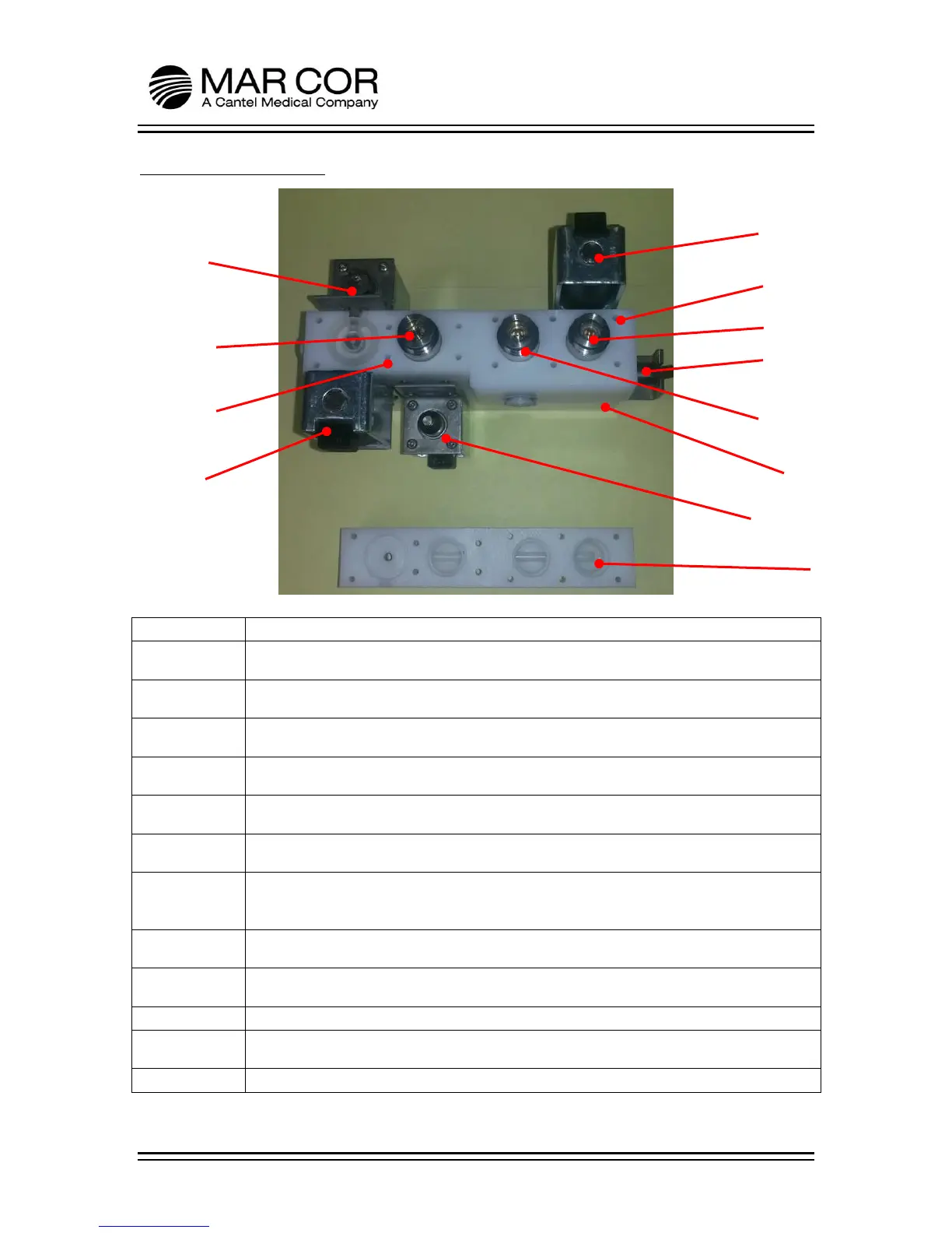
7.1.8 Main Manifold
Valve body A+B. Provides internal flow paths for drain, recycle and product water and
contains parts of CK1, CK2, CK3 and SV3.
Valve body C. Provides flow paths for the waste water and contains parts of CK1, CK2
and SV2.
Valve body D. Provides flow paths for waste water and feed water and contains the
feed conductivity probe WP1. It contains parts of SV1, SV4 and SV2.
Valve body E. Provides flow paths for waste and product water it contains parts of SV1,
SV3, SV4 and CK3.
Solenoid valve 1. Inlet water solenoid valve. Opens to allow supplied water to enter the
RO.
Solenoid valve 2. Concentrate water solenoid valve. Closed during run mode. Has
orifice hole to allow controlled flow of water through when valve is closed.
Solenoid valve 3. Product divert solenoid valve. Opens to supply product water to the
dialysis machine. Stays closed for flush or if product water quality is above the set
point.
Solenoid valve 4. Pump isolation solenoid valve. Controls the source of the pump feed
water between the internal tank and RO feed water.
Check valve 1. Concentrate water check valve. Prevents backflow of water into the
membrane.
Check valve 2. Waste water check valve. Prevents backflow of waste water into the RO.
Check valve 3. Recycle water check valve. Allows concentrate water to feed the pump
during low feed pressure conditions.
Feed water conductivity sensor. Monitors the quality of the feed water.