2B-6 90-13645--2 495ELECTRICAL AND IGNITION
Standard Stator (Alternator Coils)
9 Amperes Output
IMPORTANT: Rectifier must be functioning prop-
erly for accurate test results to be obtained.
1. If engine is equipped with a voltage regulator,
disconnect voltage regulator leads at rectifier;
reinstall hex nut on rectifier terminal that has
yellow stator lead.
2. Remove red wire from (+) terminal of rectifier.
3. Connect RED (+) ammeter lead to rectifier (+) termi-
nal and BLACK (–) ammeter lead to red rectifier
wire.
4. Run engine at 3000 RPM.
5. Meter should read 7 - 9 amperes; if not, replace
stator.
16 Amp Alternator System Test
(LARGE FINNED VOLTAGE
REGULATOR/RECTIFIER)
1. Check battery voltage at battery with engine
running.
2. If battery voltage is above 14.5 volts, replace volt-
age regulator/rectifier. Check condition of battery
as overcharging may have damaged battery.
3. If battery voltage is below 14.5 volts, charge bat-
tery; refer to “Charging a Discharged Battery”,
preceding. If battery can NOT be satisfactorily
charged, replace battery.
4. If battery accepts a satisfactory charge, check
battery voltage while cranking engine; refer to
“Charging a Discharged Battery”, preceding. If
cranking voltage is not acceptable, replace battery.
5. If cranking voltage is acceptable, disconnect RED
harness wire from center terminal.
6. Secure RED wire (d) on terminal (c) using hex nut.
7. Connect RED (+) ammeter lead to terminal (c)
and BLACK (–) ammeter lead to RED harness
wire (b).
8. Secure wires away from flywheel.
IMPORTANT: For accurate test results the voltage
at battery with engine running, in next step, must
be 13.5 volts or less. It may be necessary to oper-
ate electrical accessories to drop voltage to 13.5
volts or less.
9. With engine running at the indicated RPM’s, the
ammeter should indicate the following approxi-
mate amperes:
RPM
IDLE
1000
2000
3000
AMPERES
2
10
17
18
10. If ammeter indicates approximately 18 amperes
at 3000 RPM, this indicates the charging system
is functioning properly and the battery is being
discharged because the amperage draw on the
system is greater than the amperage output of the
system.
11. If ammeter reads less than 18 amperes, test the
stator; refer to “Stator Ohms Test (Alternator Coils
Only)” [18 Ampere Stator], preceding. If stator
tests OK, replace voltage regulator/rectifier.
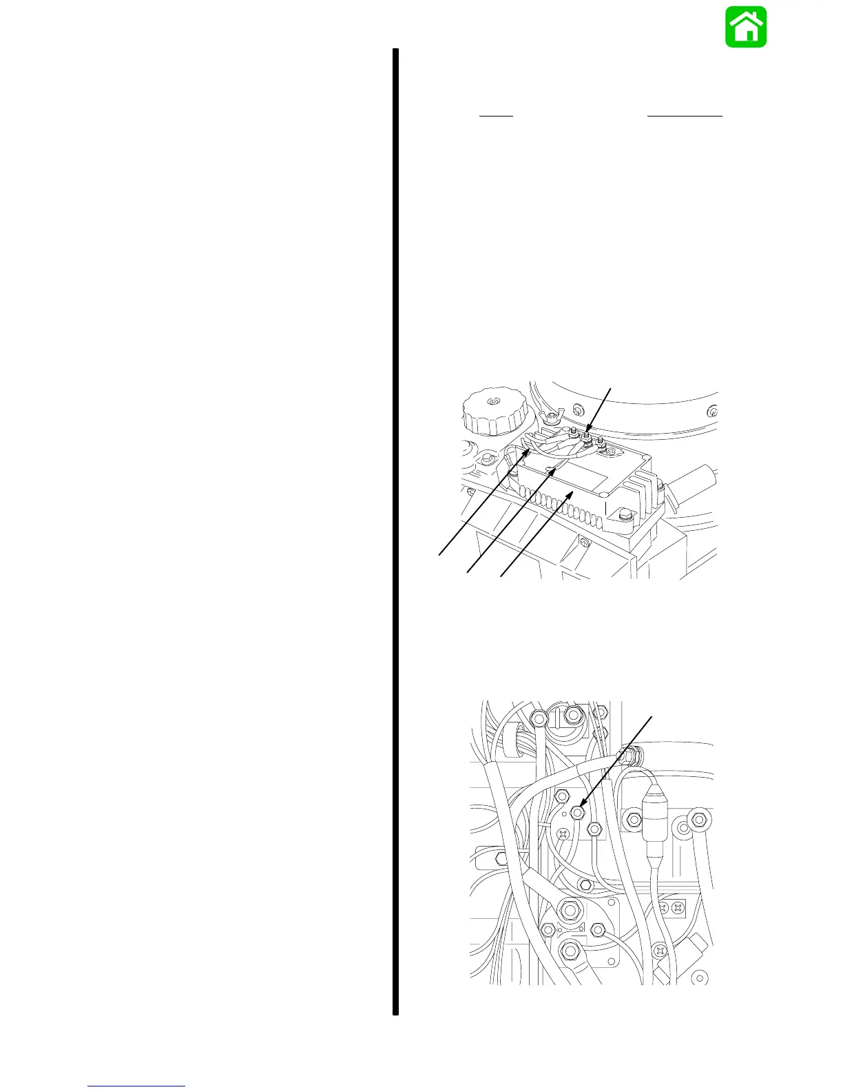
21619
a
b
c
d
a - Voltage Regulator/Rectifier
b - RED Harness Wire
c - Center Terminal
d - RED Sense Lead
NOTE:
If one or more of the 3 terminals on the termi-
nal block are shorted to ground, the battery charging
system output will be reduced.
26001
a
a - Terminal Block