6C-26 90-13645--2 495POWER-TRIM
CHECKING AND CLEANING COMMUTATOR
If commutator is worn it can be turned down on an ar-
mature conditioner tool or on a lathe.
Clean commutator with “00” sandpaper.
a
a - Commutator
Power Trim System
Reassembly
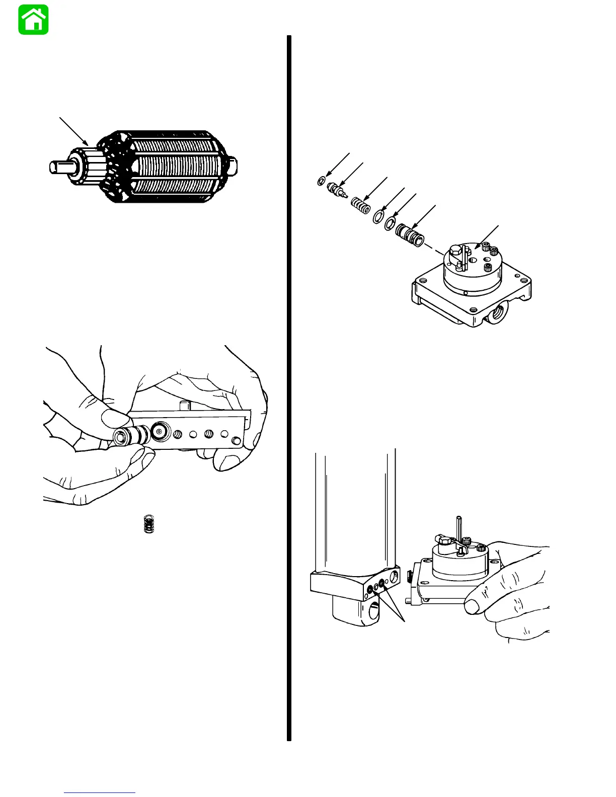
Manifold Installation
IMPORTANT: Install spring, check valve and
O-ring into manifold. Position components in
place using sleeve to seat in place.
50999
1. Install check valve components into pump man-
ifold.
IMPORTANT: Sleeve (d) is chamfered on I.D. on
end opposite drilled cross hole. Install spool (e)
(with O-ring installed) from chamfered end of
sleeve to avoid possibility of damaging O-ring on
spool.
51560
e
a
b
d
b
b
c
a - Manifold and Pump
b - O-ring (3)
c - Spring
d - Sleeve
e - Spool
2. Install O-rings on cylinder and secure manifold
assembly to cylinder using screws. Torque screws
to 100 lb. in. (11.3 N·m).
51486
a
a - O-ring (2)