6A-14 POWER TRIM 90-13645--2 495
Battery Voltage Indicated:
D Check “Down” solenoid terminals for
loose or corroded connections.
D Check BLACK ground wire (on “Down”
solenoid) for corrosion or open.
D Test “Down” solenoid. Refer to “Motor and
Electrical Tests,” see Index.
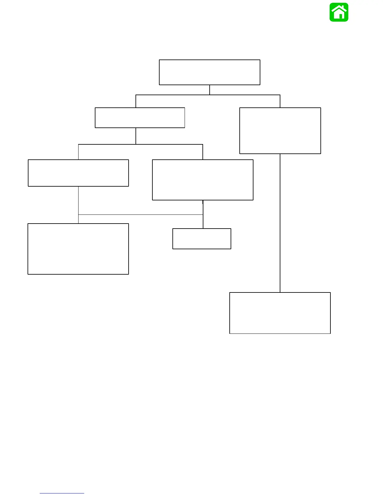
Troubleshooting the “Down” Circuit
(When “Up” Circuit Is OK)
Connect Voltmeter RED lead to Point 1 and
BLACK lead to ground.
Depress the “Down” trim button.
No Voltage Indicated:
Connect Voltmeter RED lead to
Point 4 and BLACK lead to
ground. Depress “Down” trim
button. If battery voltage is
indicated, wire is open between
Points 4 and 1.
Battery Voltage Indicated:
D Connect Voltmeter RED lead to Point 2.
D Depress “Down” trim button.
No Voltage Indicated:
Connect Voltmeter RED lead to Point 5. If
battery voltage is indicated, trim switch is
faulty. If no battery voltage, check for loose
or corroded connection at Point 5 or open
circuit in wire supplying current to Point 5.
Battery Voltage Indicated:
Connect Voltmeter RED lead to Point 9.
No Voltage Indicated:
There is an open circuit between Point 9 and
positive (+) battery terminal.
D Check for loose or corroded connections.
D Check wires for open.
No Voltage Indicated:
Solenoid is defective.
Remote Controls With or Without Trailer Buttons