90-13645--2 1095 2A-5ELECTRICAL AND IGNITION
IGNITION COIL TEST
IMPORTANT: Ohmmeter tests can only detect cer-
tain faults in the ignition coil. Replace ignition
coil, if ohmmeter readings (listed in chart, follow-
ing) are not as specified. If coil tests OK, and coil
is still suspected of being faulty, use Multi-Meter/
DVA Tester (91-99750) or a voltmeter (capable of
measuring 400 volts DC, or higher) and Direct
Voltage Adaptor (91-89045) to thoroughly check
coil.
1. Disconnect wires from coil terminals.
2. Pull spark plug lead out of coil tower.
3. Use an ohmmeter and perform the following tests.
Test Leads
Resistance
(OHMS)
Scale Reading
(x__________)
Between (+) and
(–) Coil Terminals
.02-.04*
.02-.04*
(R x 1)
Between Coil Tower and
(–) Coil Terminal
800-1100**
8-11**
(R x 100)
* The primary DC resistance of these coils generally is less than
one (1) OHM. If a reading resembling a short is obtained, this
would be acceptable.
** Copper wire is an excellent conductor, but it will have a notice-
able difference in resistance from cold to hot temperatures.
Reasonable variations from these readings are acceptable.
4. If meter readings are not as specified, replace
ignition coil.
TRIGGER TEST (3 CYLINDER)
1. Disconnect all trigger leads from switch box.
2. Use an Ohmmeter and perform the following
tests.
Test Leads
Resistance
(OHMS)
Scale Reading
(x__________)
Between Brown Trigger Lead
and White/Black Trigger Lead
1100-1400
11-14
(R x 100)
Between White Trigger Lead
and White/Black Trigger Lead
1100-1400
11-14
(R x 100)
Between Violet Trigger Lead
and White/Black Trigger Lead
1100-1400
11-14
(R x 100)
NOTE:
Above readings are for a cold engine (room
temperature). Resistance will increase slightly, if en-
gine is warm.
3. If meter readings are not as specified, replace
trigger.
TRIGGER TEST (4 CYLINDER)
1. Disconnect all trigger leads from switch box.
2. Use an Ohmmeter and perform the following
tests.
Test Leads
Resistance
(OHMS)
Scale Reading
(x__________)
Between Brown Trigger Lead
and Black Trigger Lead
700-1000
7-10
(R x 100)
Between White Trigger Lead
and Violet Trigger Lead
700-1000
7-10
(R x 100)
NOTE:
Above readings are for a cold engine (room
temperature). Resistance will increase slightly, if en-
gine is warm.
3. If meter readings are not as specified, replace
trigger.
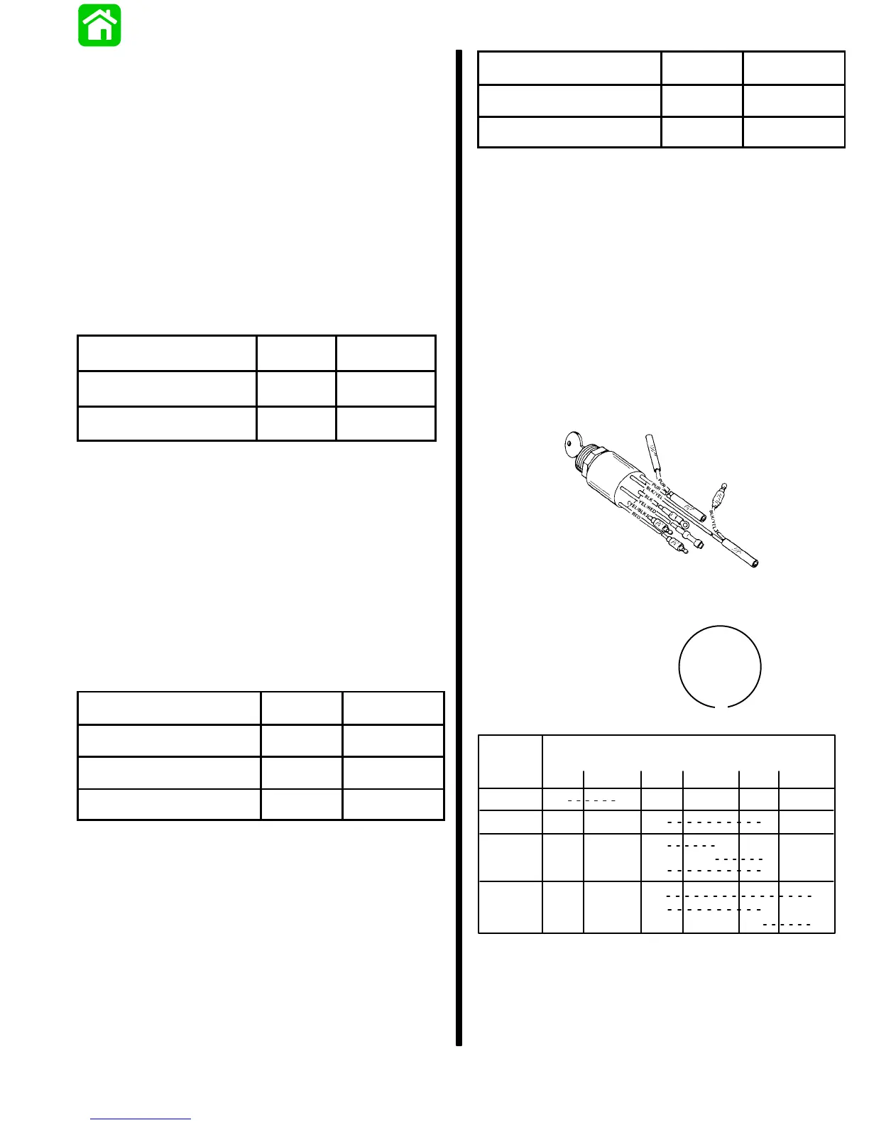
IGNITION (KEY) SWITCH TEST
1. Disconnect remote control wiring harness and
instrument panel connector.
NOTE:
Wiring diagram for control boxes is located in
SECTION 2D.
2. Set ohmmeter on R x 1 scale for the following
tests:
COMMANDER 2000 KEY SWITCH
23894
COMMANDER KEY SWITCH
BLK D BLACK
PURD PURPLE
REDD RED
YEL D YELLOW
(PUR)
(BLK)
(YEL/RED)
(YEL/BLK)
(RED)
(BLK/YEL)
C
B
M
A
M
S
KEY
POSITION
BLK BLK/YEL RED YEL/RED PUR YEL/BLK
•
CONTINUITY SHOULD BE INDICATED
AT THE FOLLOWING POINTS:
OFF
RUN
START
CHOKE*
•
••
•
•
••
•
•
•
•
• •
•
•
* Key switch must be positioned to “RUN” or “START” and key pushed
in to actuate choke, for this continuity test.
3. If meter readings are other than specified in the
preceding test, verify that switch and not wiring is
faulty. If wiring checks OK, replace switch.