2B-4 90-13645--2 495ELECTRICAL AND IGNITION
Optional Voltage
Regulator Test
1. Check battery voltage at
battery with engine running.
2. If battery voltage is above 14.5 volts, replace volt-
age regulator. Check condition of battery as over-
charging may have damaged battery.
3. If battery voltage is below 14.5 volts, charge bat-
tery; refer to “Charging a Discharged Battery”,
preceding. If battery can NOT be satisfactorily
charged, replace battery.
4. If battery accepts a satisfactory charge, check
battery voltage while cranking engine; refer to
“Charging a Discharged Battery”, preceding. If
cranking voltage is not acceptable, replace bat-
tery.
5. If cranking voltage is acceptable, disconnect end
of RED wire (located between rectifier (+) terminal
and starter solenoid) from rectifier. Secure RED
wire (from voltage regulator) to rectifier (+) termi-
nal with hex nut.
6. Connect RED (+) ammeter lead to (+) terminal of
rectifier and BLACK (–) ammeter lead to RED wire
(disconnected in last step).
IMPORTANT: For accurate test results the voltage
at battery with engine running, in next step, must
be 13.5 volts or less. It may be necessary to oper-
ate electrical accessories to drop voltage to 13.5
volts or less.
7. Run engine at 3000 RPM.
8. Meter should read between 7 - 9 amperes.
9. If meter reads 7 - 9 amperes, this indicates the
charging system is functioning properly and the
battery is being discharged because the amper-
age draw on the system is greater than the amper-
age output of the system.
NOTE:
With engine running at the following RPM’S,
the ammeter should indicate the following approxi-
mate amperes:
RPM AMPERES
IDLE 1
1000 4
2000 8
3000 9
10. If the meter reads less than 7 amperes, test the
stator; refer to “Standard Stator (Alternator Coils)
Amperes Output”, following. If stator tests OK, re-
place voltage regulator.
Battery Charging System
(9 Ampere Alternator)
Description
The battery charging system components are the sta-
tor, rectifier, and battery. Alternating current (gener-
ated in stator alternator coils) flows to the rectifier,
which changes the alternating current to direct cur-
rent for charging the battery.
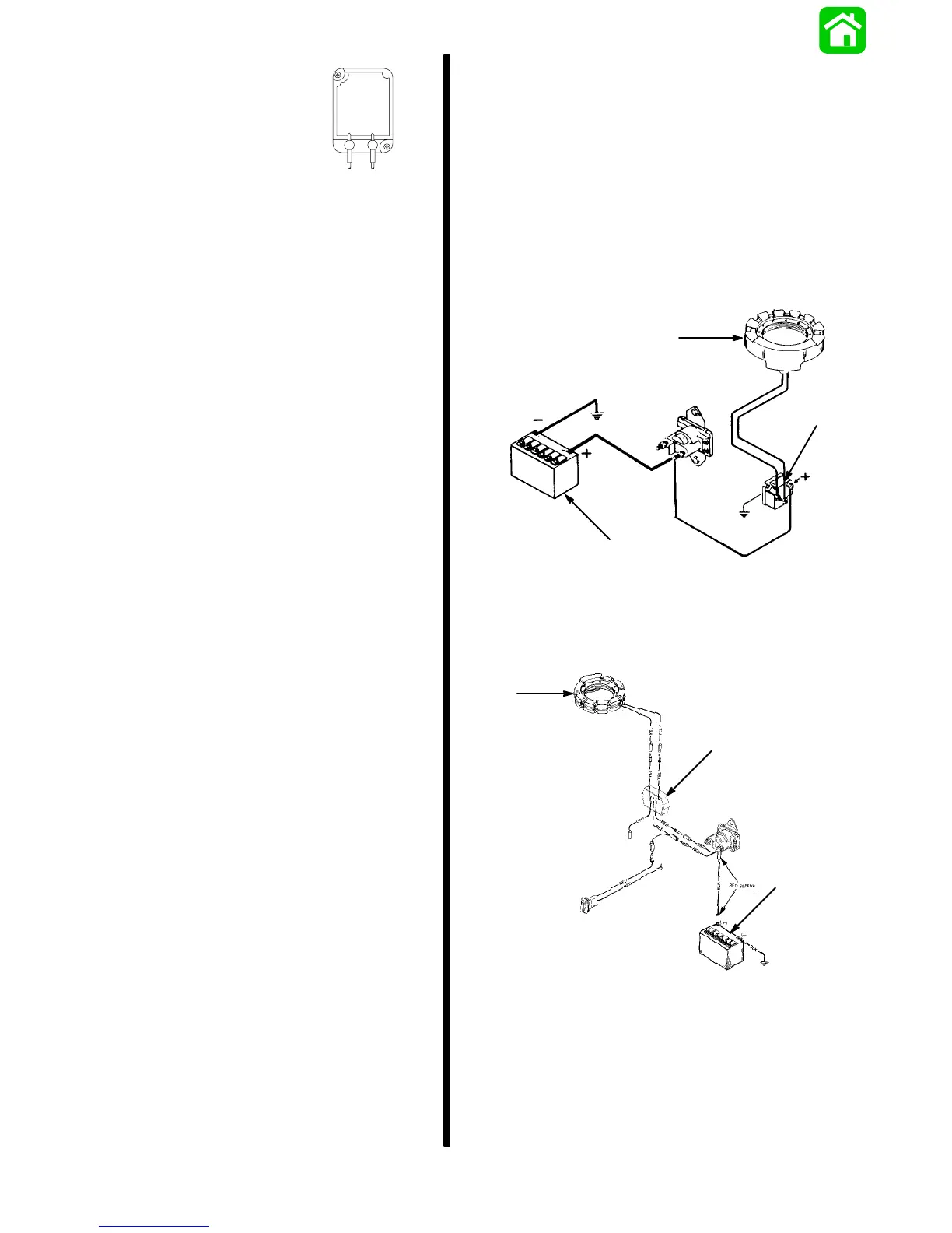
MODELS EQUIPPED WITH RECTIFIER
a
b
c
a - Stator
b - Rectifier
c - Battery
MODELS EQUIPPED WITH REGULATOR
b
c
a
a - Stator
b - Regulator
c - Battery
The charging system may be damaged by: 1) re-
versed battery cables, 2) running the engine with bat-
tery cables disconnected and stator leads connected
to rectifier, and 3) an open circuit, such as a broken
wire or loose connection.