2D-790-13645--2 495 ELECTRICAL AND IGNITION
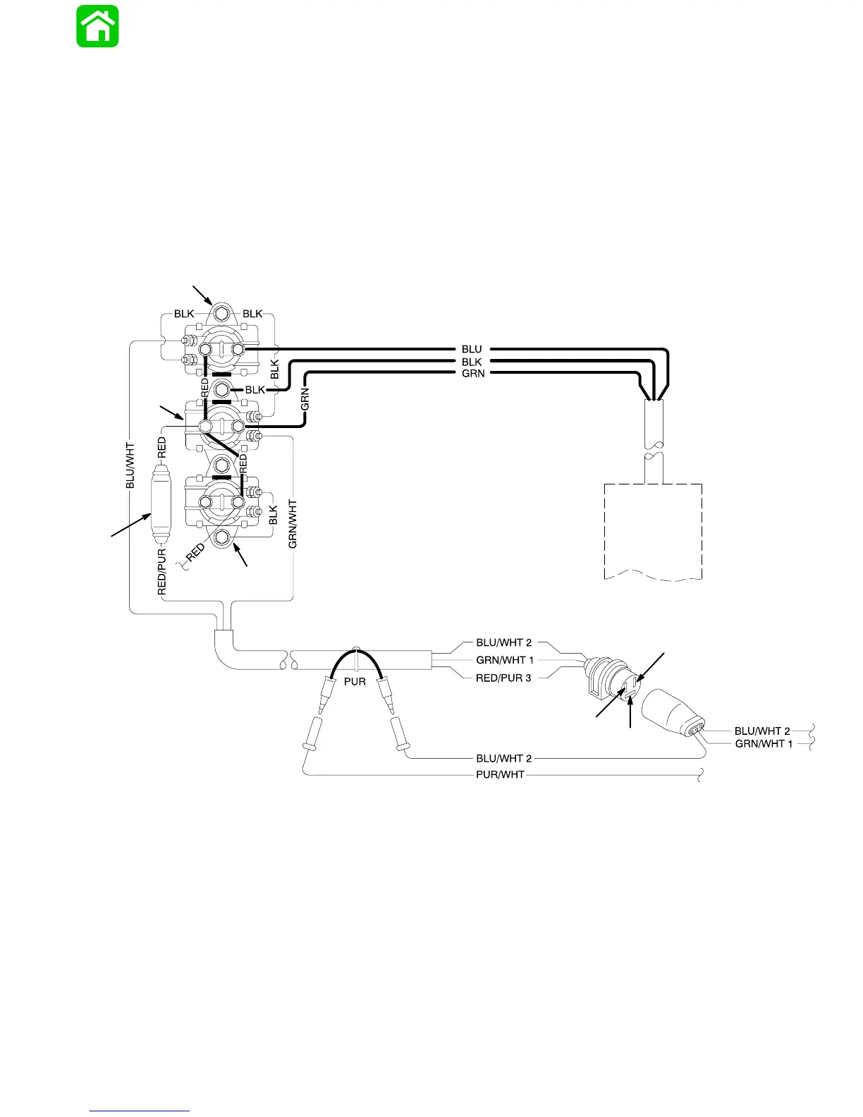
Power Trim System Wiring Diagram (3 Cylinder Models
Using COMMANDER Side Mount Remote Control)
23884
BLK BLACK
BLU BLUE
GRN GREEN
PUR PURPLE
RED RED
WHT WHITE
a
b
c
d
e
f
g
g
1
2
3
a - Power Trim Pump Motor
b - Trim Solenoid “UP”
c - Trim Solenoid “DOWN”
d - Engine Starter Motor Solenoid
e - Fuse Holder (20 Amp Fuse)
f - Red (+) Battery Cable
g - Wires from Remote Control