2D-4 90-13645--2 495ELECTRICAL AND IGNITION
Engine Wiring Diagram
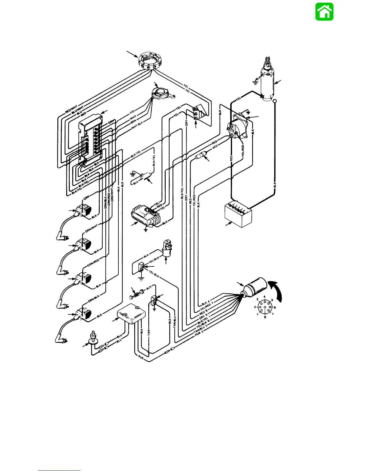
(4 Cylinder Models)
50389
BLK BLACK
BLU BLUE
BRN BROWN
GRY GRAY
GRN GREEN
PUR PURPLE
RED RED
TAN TAN
VIO VIOLET
WHT WHITE
YEL YELLOW
a
b
c
d
e
f
h
i
k
l
m
n
o
p
q
r
s
g
p
o
j
a - Stator
b - Trigger
c - Switch Box
d - Ignition Coil Cylinder No. 1
e - Ignition Coil Cylinder No. 2
f - Ignition Coil Cylinder No. 3
g - Ignition Coil Cylinder No. 4
h - Mercury (Tilt) Stop Switch
i - Starter Motor
j - Starter Solenoid
k - Voltage Regulator/Rectifier
l - Fuse Holder (20 Amp Fuse)
m- Battery
n - Wiring Harness Connector
o - Enrichment Valve
p - Terminal Block
q - Temperature Switch – Opens [170F
8 (77C 8)]
Closes [190F
8 (88C 8)]
r - Low Oil Warning Module
s - Low Oil Sensor