2D-8 90-13645--2 495ELECTRICAL AND IGNITION
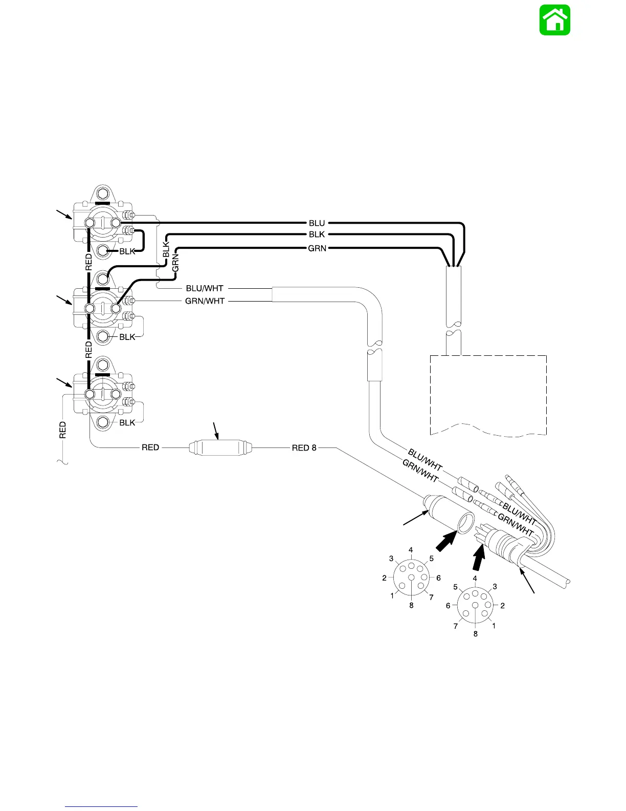
Power Trim System Wiring Diagram (4 Cylinder Models
Using COMMANDER 2000 Side Mount Remote Control)
23885
BLK BLACK
BLU BLUE
GRN GREEN
RED RED
WHT WHITE
a
b
c
d
e
f
g
h
a - Power Trim Pump Motor
b - Trim Solenoid “UP”
c - Trim Solenoid “DOWN”
d - Engine Starter Motor Solenoid
e - Red (+) Battery Cable
f - Fuse Holder (20 Amp Fuse)
g - Engine Wiring Harness Connector
h - Remote Control Wiring Harness Connector