8 ESM303-003 SAFETY SHIELD INSTALLATION
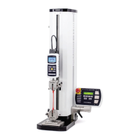
The optional ESM303-003 safety shield can protect the
operator against the dangers of airborne debris resulting
from compression and tension force testing. Follow these
assembly and usage instructions:
1. The safety shield is shipped fully assembled.
Remove it from the box and remove the packaging.
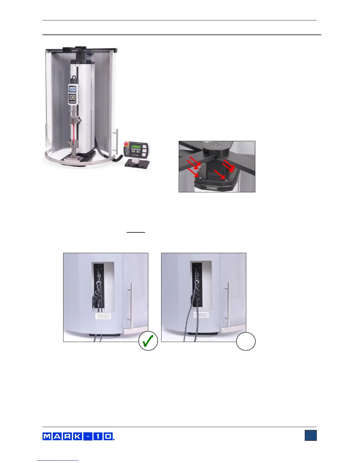
2. Position the mounting bracket on top of the ESM303
column, aligning the thru holes with the
corresponding threaded holes at the top of the
ESM303 test stand column. Fasten the six provided
socket head screws, as shown below:
3. Plug the interlock cable into the corresponding connector in the rear of the test stand column,
labeled “AUX. LIMITS”, as shown in the
Connections and Outputs
section.
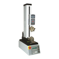
4. Route all cables, such as the test stand power cable and control panel cable, underneath the
shield, as shown below.
Do not
route cables through the cutout in the sheet metal cover. Doing
so can result in damage to the cables while the door is rotating past this area. The cutout is
provided only for hand access to the connector panel.
5. The door may be opened in the clockwise or counter-clockwise direction. Magnetic detents are
provided for the closed position. If the interlock cable is plugged in, the ESM303’s control panel
will display the message “SHIELD OPEN” when the door is open. The ESM303 cannot be
operated in this state, however, the FollowMe
TM
function may be used to adjust the crosshead
position for sample loading.
Note that the following minimum ESM303 firmware versions are required: Front: 2.02.08 / Main:
2.02.07. With prior versions, the FollowMe
TM
function will not operate while the door is open.
Contact Mark-10 for upgrade instructions.