Further instructions for configuring communication parameters may be found in the Test Function Setup
section.
If PC control is used, a full listing of available ASCII commands may be found in the Operating Modes
section.
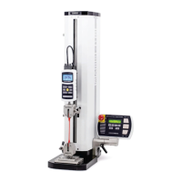
2.5 Installing a force gauge or indicator with load cell
2.5.1 ESM303
Once the test stand is in a stable and secure position, install a force gauge by mating the dowel pin in the
force gauge mounting plate with the blind hole in the rear of the force gauge’s housing. Use the four
thumb screws to secure the gauge. Grips and fixtures may be threaded onto the force gauge and test
stand base.
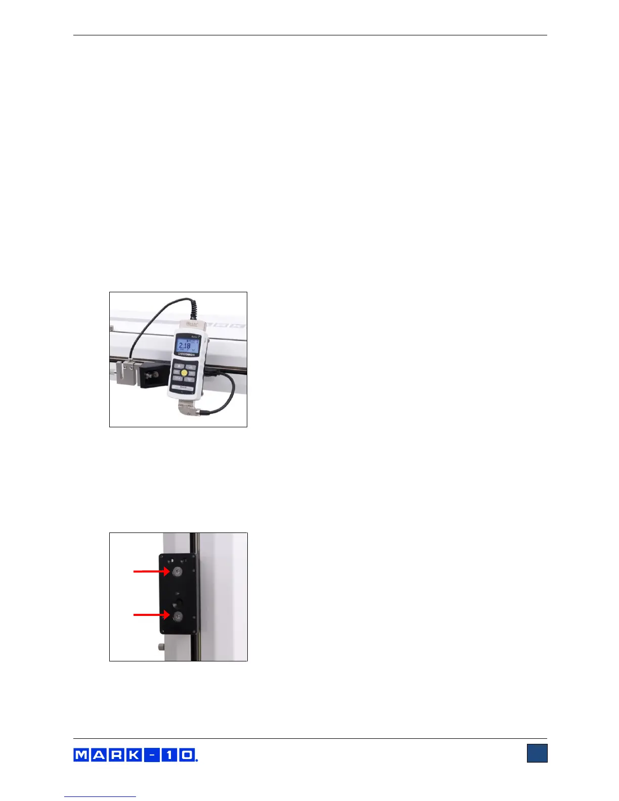
2.5.2 ESM303H
1. Once the test stand is in a stable and secure position, install an indicator via four thumb screws.
2. Install a load cell to the crosshead using the supplied hardware, and insert the Plug & Test
TM
connector into the indicator, as shown in the image below:
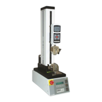
2.6 Installing an indicator / load cell mounting kit (optional for ESM303)
The optional AC1062 mounting kit is available to mount a Series R01 or Series R03 load cell (force
sensor) and an indicator onto the crosshead, instead of a force gauge. To install, follow these
instructions:
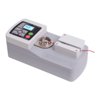
1. Remove the force gauge mounting plate by loosening the two 5/16-18 flat head screws, as shown
below:
2. Install the indicator bracket onto the side of the crosshead, utilizing two #10-32 flat head screws,
as shown below: