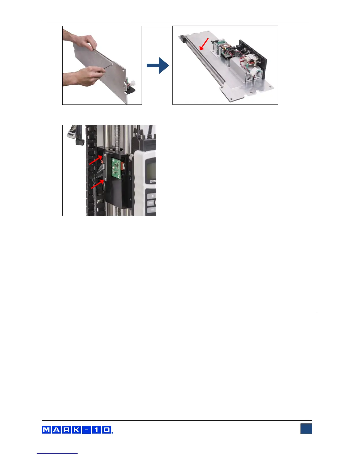
6. Install the encoder assembly to the crosshead with 2 screws, as shown in the image below:
7. Re-install all hardware and components in reverse order. Be sure to position the upper limit
switch above the crosshead and the lower limit switch below the crosshead before installing to
the electronics support plate.
9.2 Entering the activation code
Access the Function Activation menu and locate the function labeled “TRAVEL”. Obtain the request code,
and enter the activation code, a process described in the Function Activation section. After inputting the
activation code, cycle the crosshead up and down to ensure that the position indicator is incrementing
and decrementing properly.
10 SEPARATING THE COLUMN FROM THE BASE /
COLUMN EXTENSION INSTALLATION
The column may be separated from the base to accommodate alternative mounting arrangements, for
considerations such as safety, increased sample clearance, integration into existing equipment, etc. The
instructions below reference Model ESM303, however, the process is similar with the ESM303H.
10.1 Removing the base from the column
To remove the base, follow these instructions:
1. Power off the test stand and disconnect the power cable.
2. Lay the test stand on its side and remove the 6 screws from the underside of the base. Carefully
remove the base from the frame. Refer to the image below.