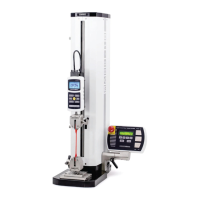
2. Install the control panel to the mounting bracket utilizing two #8-32 screws.
3. The viewing angle may be adjusted by loosening the lever, positioning the control panel, and re-
tightening the lever.
2.2.2 ESM303H
1. Install the control panel to the mounting bracket utilizing two 1/4-28 screws.
2. Install the mounting bracket to the bracket adapter with two #8-32 screws.
3. Install the bracket adapter to the edge of the test frame with two #10-32 screws. This may be
done on either the right end or the left end of the frame, where sets of #10-32 holes are provided.
4. The viewing angle may be adjusted by loosening the lever in the rear of the bracket, positioning
the control panel, and re-tightening the lever.
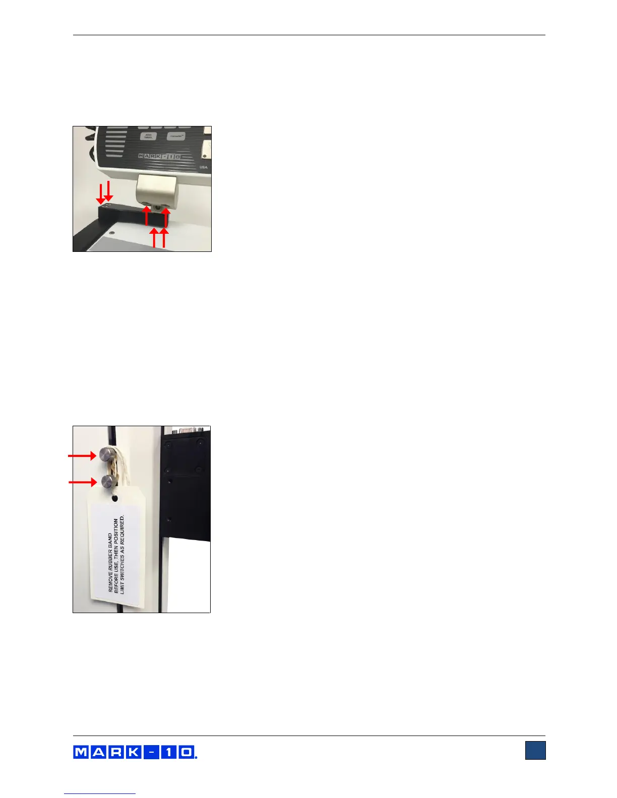
2.3 Limit switches
Upper and lower limit switches are supplied to stop travel in both directions. The limit switch thumb
screws are shipped banded together, as illustrated below:
Remove the rubber band and instructional tag before use. Refer to later sections for more detailed
information about limit switches.