Models ESM303 & ESM303H Test Stands User’s Guide
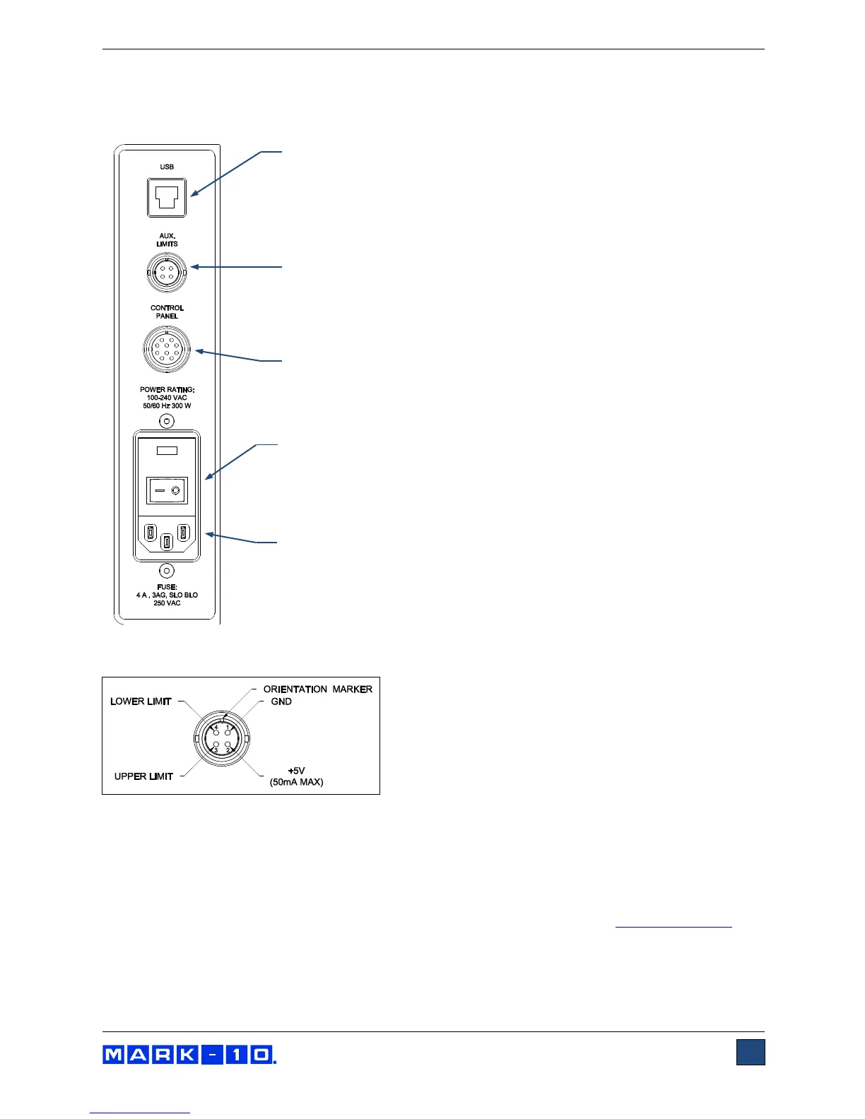
2.4 Connections and outputs
The following connections and outputs are supplied in the rear of the test stand, as shown in the
illustration below:
USB connector
Outputs force only or force and travel data (optional) via USB. Also allows
for PC control (optional). Plug one end of the USB cable into this connector,
and the other end into a PC’s USB port. Refer to the next sub-section for
driver installation information.
Auxiliary limit switch connector
For interfacing an external limit switch, such as an interlock for a machine
guard door. A pin diagram is shown in the next sub-section.
Control panel cable connector
Plug the cable into this connector.
Power switch
Refer to the Connecting Power sub-section for important safety
information.
Power plug receptacle
Plug the power cord in here. Refer to the Connecting Power sub-section
for important safety information.
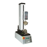
2.4.1 Auxiliary limit switch pin diagram
Note that when pins 3 and 4 are not connected, the auxiliary limits are inactive. When the +5V from pin 2
is connected to either pin 3 or pin 4, the respective limit becomes active and the crosshead is prevented
from movement in that direction.
2.4.2 USB driver installation
To use this output, install the USB driver provided on the Resource CD, labeled “Mark-10 USB Device”.
Installation instructions may also be found on the CD or may be downloaded from www.mark-10.com.
Caution!
Install the USB driver before physically connecting the tester to a PC with the USB cable.