acquisitions of larger objects
(if more than one camera is required to span over the complete image, like in the textile and
printing industry).
•
To solve this task, the mvBlueFOX3 offers timers that can be used to generate pulse at regular
intervals. This pulse can be connected to a digital output. The digital output can be connected digital
to the digital input of one or more cameras to use it as a trigger.
18.10.1.2 Connecting the hardware
One camera is used as master (M), which generates the trigger signal. The other ones receive the
trigger signal and act as slaves (S).
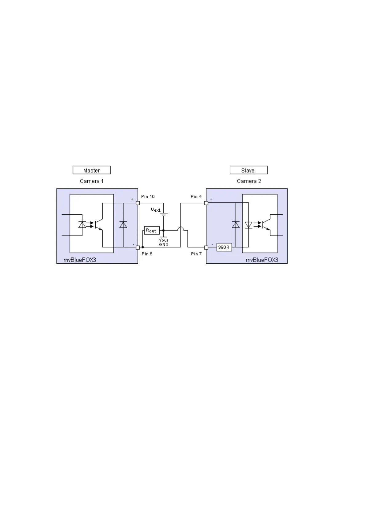
Connecting the cameras The connection of the mvBlueFOX3 cameras should be like this:
Figure 1: Master - Slave connecting
Symbol Comment Input voltage Min Typ Max Unit
U
ext.
External power 3.3 30 V
R
out
Resistor digital output 2 kOhm
18.10.1.3 Programming the acquisition
You will need two timers and you have to set a trigger.
Start timer
Two timers are used for the "start timer". Timer1 defines the interval between two triggers. Timer2
generates the trigger pulse at the end of Timer1.
The following sample shows a trigger
which is generated every second and•
the pulse width is 10 ms:•
#include <mvIMPACT_CPP/mvIMPACT_acquire.h>
#include <mvIMPACT_CPP/mvIMPACT_acquire_GenICam.h>
...
18 Use cases
246