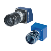
Figure 7: mvBlueFOX3-2xxx-2xxx mounting holes
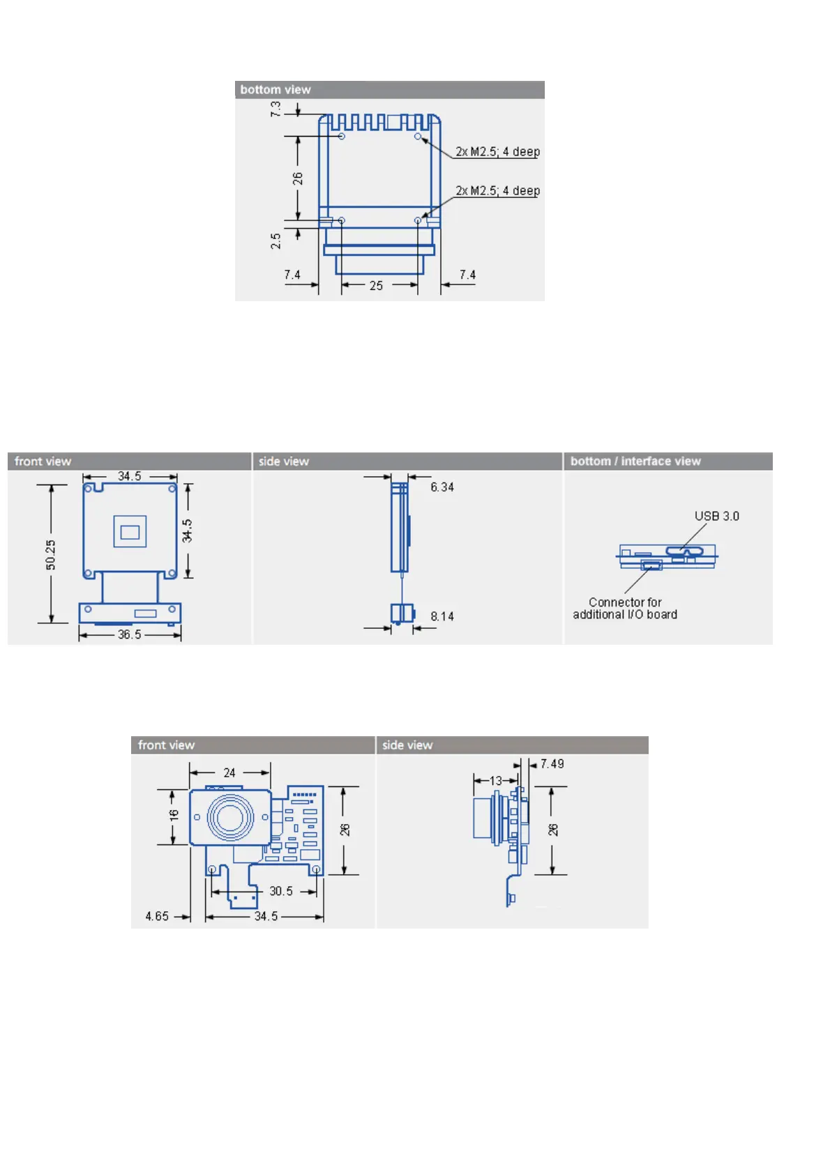
8.1.3 Model without housing (-M1)
Warning:
In combination with the connectors, the mechanical stress needs to be limited.
Figure 8: mvBlueFOX3-M dimensions and connectors
8.1.3.1 I/O board for mvBlueFOX3-M (mvBlueFOX3-IO)
Figure 9: mvBlueFOX3-M dimensions of additional I/O board
The following figure shows, how the additional I/O board gets connected correctly.
Warning:
Since the connector of the I/O board will also fit upside down, you have to be careful while
connecting. Otherwise you can destroy the camera and / or the I/O board. As show in the
8 Technical data
54