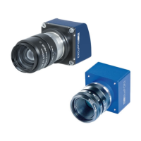
figure, if the I/O board was connected correctly, you can bend the I/O board on the back of
the sensor board. Then the I/O board connector will point to the opposite direction as the
sensor.
Figure 10: mvBlueFOX3-M connected I/O board
The pinning of the mvBlueFOX3-IO is described in the chapter Circular connector male (Power /
Digital I/O).
Note:
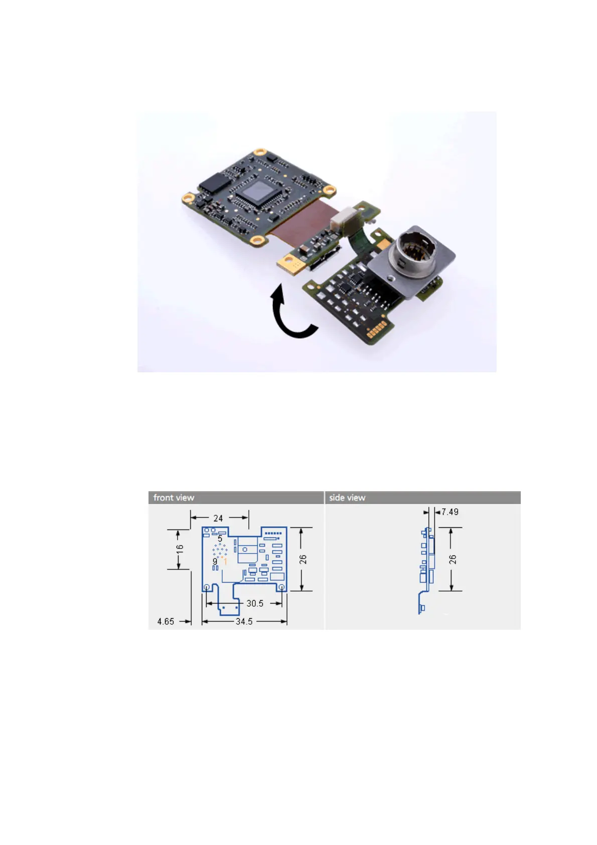
It is also available to purchase the I/O board without Hirose connector as "mvBlueFOX3-IO
NC" (NC = not connected). The pinning is provided in the figure:
Figure 11: mvBlueFOX3-M dimensions of additional I/O board without Hirose
connector.
8.1.4 Model without housing (-M2)
Warning:
In combination with the connectors, the mechanical stress needs to be limited.
8 Technical data
55