CSP-HMI-3 MD Helicopters, Inc.
MAINTENANCE MANUAL
[ Main Menu ]
[ HMI−3 Book TOC ]
[ Chapter 95 TOC ]
Page 902
Revision 7
95-10-20
The information disclosed herein is proprietary to MD Helicopters, Inc.
Neither this document nor any part hereof may be reproduced or transferred to
other documents or used or disclosed to others for manufacturing or any other
purpose except as specifically authorized in writing by MD Helicopters, Inc.
Copyright © 1999−2016 by MD Helicopters, Inc.
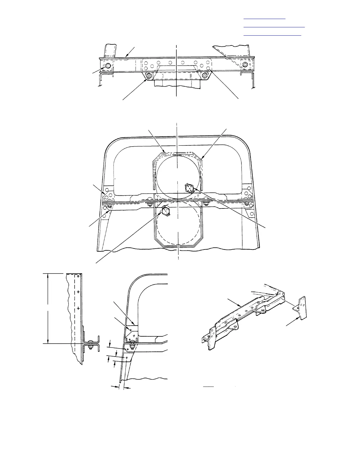
G95-1017A
SUPPORT ASSEMBLY
0.198-0.204 INCH
(5.0292-5.1816 MM)
DIAMETE
R
2 HOLES TO MATCH
BRACKET & BRACE
SCREW, WASHER, NUT
(2 PLCS)
SCREW, WASHER, NUT
(2 PLCS)
SYMMETRY
ABOUT C
L
CLAMP FASTENER HOLES FOR
369H90041 & 369H90042
INDICATOR KIT INSTALLATION
STRIP
CLAMP ASSEMBLY
ATTITUDE
GYRO
”T” BRACKET
SUPPORT ASSEMBLY
DIRECTIONAL
GYRO
J506
J507
STIFFENER
BRACKET
SUPPORT ASSEMBLY
”T” BRACKET
EXISTING
RIVETS
(NOTE)
4.75 INCH
(12.065 CM)
0.06 INCH
(1.524 MM)
0.28 INCH
(7.112 MM)
0.28 INCH
(7.112 MM)
NOTE:
5 PLACES - REMOVE AND REPLACE AS REQUIRED.
Figure 901. T−brackets and Support Assembly Installation (Slim−Line Instrument Panel)