CSP-HMI-3MD Helicopters, Inc.
MAINTENANCE MANUAL
[ Main Menu ]
[ HMI−3 Book TOC ]
[ Chapter 96 TOC ]
96-40-00
Page 217
Revision 11
The information disclosed herein is proprietary to MD Helicopters, Inc.
Neither this document nor any part hereof may be reproduced or transferred to
other documents or used or disclosed to others for manufacturing or any other
purpose except as specifically authorized in writing by MD Helicopters, Inc.
Copyright © 1999−2016 by MD Helicopters, Inc.
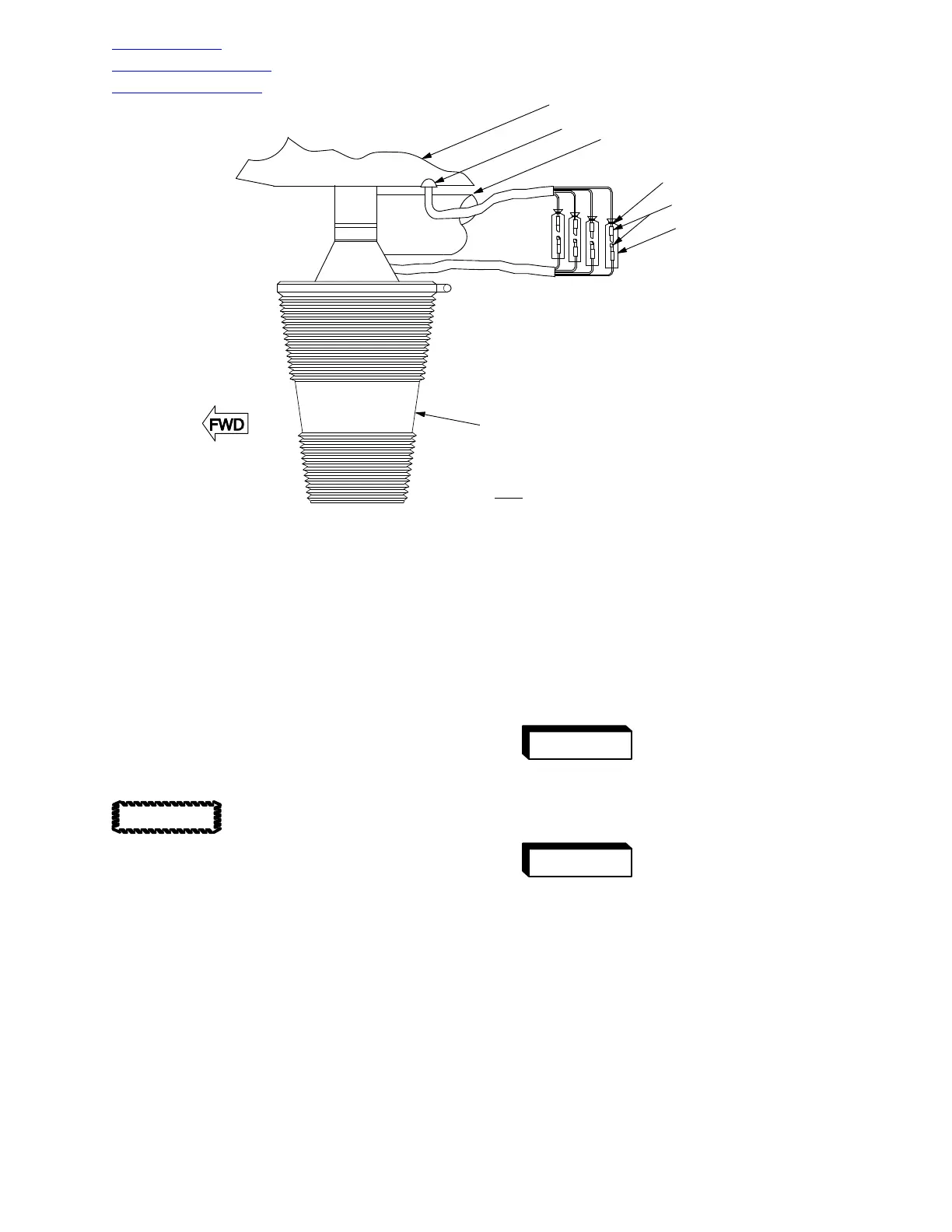
LENS
CLEAR VINYL TUBING
SPLICES
TIE WRAP
TAILBOOM
GROMMET
SKID TUBE
NOTE
: WIRING INSTALLATION TYPICAL FOR
UPPER OR LOWER TAIL ANTI-COLLISION LIGHT.
G96-4020
Figure 206. Anticollision Light Sleeving Installation
(d). Slide clear vinyl tubing back over
each splice and tie wrap each end.
(e). Carefully slide splices and wiring
into tail boom or horizontal stabilizer
and install grommet if removed.
(f). Attach base-plate to horizontal
stabilizer or tailboom mounting
bracket using attaching hardware.
(g). Install lens on base-plate assembly
using clamp.
Reversed polarity connections
can cause damage to this equip
ment. For connection information, refer to
wiring diagram (Ref. Sec. 96-00-00).
(h). Connect electrical power and check
operation of strobe anticollision
lights.
O. Strobe Anticollision Light Power Supply
The strobe anticollision light power supply is a
solid-state unit that is mounted on the aft side
of the forward bulkhead in the right or left, as
appropriate, under-floor area in the pilot's
compartment. This unit converts 28 Vdc input
to pulsating high voltage output required for
strobe operation and controls flashing rate at
90 flashes (alternating) per minute. The unit
receives 28 Vdc power through the ANTI-
COLL switch/circuit breaker on the instru
ment panel.
P. Strobe Anticollision Light Power Supply
Replacement
(Ref. Figure 205)
Ensure that all electrical
power is OFF.
(1). Open access door in right or left side
floor of pilot's compartment as appropri
ate.
High voltage is used in pow
er supply-to strobe light cir
cuits. Circuits must be OFF for at least
10 minutes to allow voltage bleed-off
prior to disconnecting wiring or disas
sembling unit.
(2). Disconnect electrical plugs, power lead
splice and ground connection.
(3). Remove attaching hardware that
secures power supply to bulkhead and
remove power supply unit.
(4). Place replacement power supply in
position and secure.
CAUTION
WARNING
WARNING