CSP-HMI-3MD Helicopters, Inc.
MAINTENANCE MANUAL
[ Main Menu ]
[ HMI−3 Book TOC ]
[ Chapter 96 TOC ]
96-45-00
Page 205
Revision 11
The information disclosed herein is proprietary to MD Helicopters, Inc.
Neither this document nor any part hereof may be reproduced or transferred to
other documents or used or disclosed to others for manufacturing or any other
purpose except as specifically authorized in writing by MD Helicopters, Inc.
Copyright © 1999−2016 by MD Helicopters, Inc.
4
3
P506E10
P506X10
12
SEARCHLIGHT PWR
CB127
L557A10 BLACK
GRA
Y
DS401 (LH)
WHT
DS402 (RH)
WHT
1
1
2
2
A1 A2
A1 A2
20 AWG
JMPR
E27
K303K302
X2
X2
X1
X1
20 AWG JMPR
L564B20
A B
A B
L563A16-YEL
L564A16-YEL
12
S3
KEY SWITCH
K510F16
12
SEARCHLIGHT
CONT
CB128
5A
1
2
OFF
ON
S205
SEARCHLIGHT
1
2
3
XDS11
L562A20N L562A20-WHT
21
S206
L510G20-WHT
SEARCHLIGHT
STOWED
E3
L565A20N
20 AWG JMPR
CAUTION LIGHT
(PRESS-TO-TEST)
G96-4015
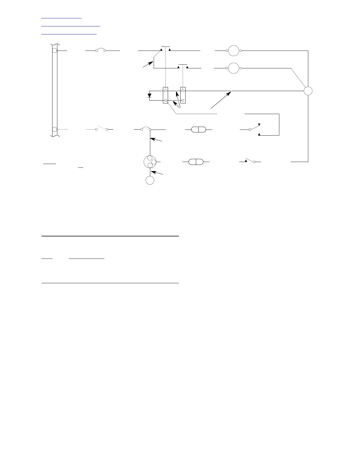
NOTES
:
1. SOLID LINES ( ) INDICATE WIRING OR
ITEM SUPPLIED WITH SEARCHLIGHT KIT.
2. DASHED LINES ( - - - ) INDICATE WIRING OR
ITEM OF HELICOPTER ELECTRICAL SYSTEM.
Figure 202. Searchlight Wiring Diagram
B. Searchlight Assembly Installation
(Ref. Figure 201)
Consumable Materials
(Ref. Section 91−00−00)
Item
Nomenclature
CM102 Solid film lubricant
CM614 Sleeving, heat-shrink
(1). Install SEARCHLIGHT ON-OFF
switch on control column as follows:
(a). Connect wiring and install switch in
housing.
(b). Install housing on control column
and secure with screws.
(2). Install SEARCHLIGHT PWR and
CONT circuit breaker panel as follows:
(a). Install SEARCHLIGHT EXT caution
light assembly on panel and connect
wiring to light assembly. If required,
replace lamp in light assembly cap on
face of panel.
(b). Install SEARCHLIGHT PWR and
CONT circuit breakers on panel and
connect wiring to circuit breakers.
(c). Install and secure lower switch and
circuit breaker panel to instrument
panel with screws.
(3). Install relays K302 and K303 on
nutplate support at bottom of fuselage
as follows:
(a). Using screws and washers, install
relays on nutplate support.
(b). Install bus with RNF100X1/2 sleeve
(CM614), IN5401 diode, jumper
wires, and wiring to relay terminals.
(4). Place searchlight control column in
floor pan, and allow control column to
extend through lower bearing plate and
support at bottom of fuselage. Do not
install bolts at this time.
(5). Hoist or jack up helicopter (Ref. Sec.
07-00-00) until landing gear skids or
floats are approximately 2 feet (61 cm)
above ground.
(6). Engage lower support column into end
of upper control column. Make certain
that slidelock pin attachment hole on