Page 4 - 4 TA3H, TA3SH & TA3.5SH
4. Description
4.4 Skip
The dumper vehicle is basically a load carrier and the skip can be used for a multitude of building/
contracting site functions, but essentially it is used for carrying free flowing materials from
excavations or demolitions and general site building activities.
On forward tip machines the skip is raised and lowered by a double acting hydraulic cylinder
mounted between the front chassis and the underside of the skip and controlled by joystick
operated control valve.
On swing skip machines the ram is mounted between the top of the turntable and the underside
of the skip.
The swing skip is mounted on a ball bearing slew ring and is rotated by twin hydraulic rams.The
swing skip must be mechanically locked in the straight ahead position to prevent movement
when travelling.
The joystick control for skip operations is positioned to the right of the drivers seat.
(1) Raised Skip
As a safety aid when working on the machine a stop is provided that fits over the skip ram when
the skip is raised. This prevents the skip lowering accidentally and causing injury. You must not
reach or work under a raised skip without the ram stop fitted.
(2) Swing Stop
On swing skip machines a locking device is used to locate the skip in the straight ahead position
when the skip is fully lowered.Before slewing to the left or right, it is necessary to raise the skip
slightly to clear the stop.
4.5 Chassis
The two part chassis is of the centre pivot articulating type and is of a design which enables both
front and rear axles to be attached directly to the chassis members.
The front and rear frames are connected in the middle by a vertical pivot in spherical bearings
and a horizontal link, which connects between the spherical bearing of the vertical pivot and an
additional spherical bearing located in the rear frame.
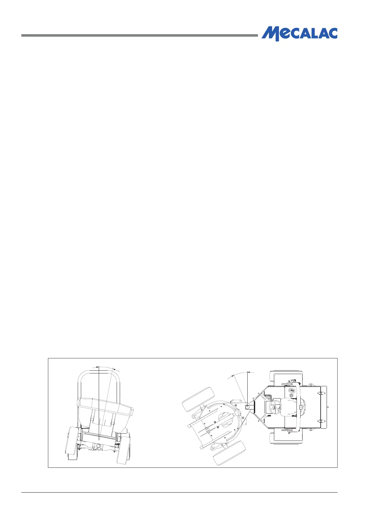
This arrangement is illustrated in Figure 4.3 and shows full movement of the chassis in both
horizontal and vertical planes, thus ensuring maximum wheel adhesion at all times
.
Figure 4.3 - Chassis Articulation
30˚
10.5˚
COV00031