Page 4 - 18 TA3H, TA3SH & TA3.5SH
4. Description
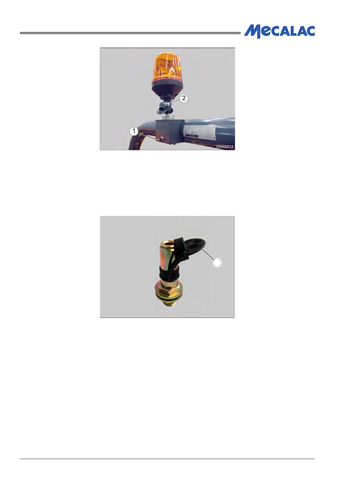
Figure 4.16 - Flashing Beacon
1. Switch
2. Securing Nut
When the beacon has been removed, the top of the mounting stem is covered by pulling the
rubber stem cap (1) over the mounting stem, Figure 4.17.
Figure 4.17 - Beacon Mounting Stem
1. Rubber Cover
(1) Storage
To help prevent damage, theft and vandalism the flashing beacon can be removed from its
working position on the ROPS and stored inside the lockable engine compartment when not
required. A dedicated mounting point, Figure 4.16, is provided. It is held in position by tightening
the nut (1).
1
COV00013