1.2.2.10 Winding (1,2,3,4) Tap
A numerical value associated with the Winding Number i.e. 1, 2, 3, 4, etc., of a transformer
differential relay. Used to define the tap setting value and test for each winding.
1.2.2.11 % Slope
A numerical value which establishes the operating characteristic of a differential relay. The
operating characteristic of the differential relay is a line, with a slope defined by the ratio of the
operating and restraint values.
1.2.2.12 % Harmonic
A numerical value which establishes the percent of harmonic restraint for a harmonic restrained
transformer differential relay. This value will be used to determine Pass/Fail during the Harmonic
Restraint test.
1.3 Touch View Interface (TVI)
The Touch View Interface is the operator’s interface for the manual operation of this unit.
Variable or value changes are performed by the touch panel keypad or by rotating the control
knob after touching the display with your finger where the change is required. See section 2.2 for
operational details.
1.4 Input Power and Control
1.4.1 Input Power
The input voltage may be from 100 to 240 VAC, 50/60 hertz. Input current required varies with
the number of output modules in use and load. The maximum input power is 2100VA. The input
is protected by an ON/OFF switch / circuit breaker.
Model 84XX-XXXXAX comes with a North
American power cord (part number 801046).
Model 84XX-XXXXEX comes with a Continental Europe power cord (part number 15021).
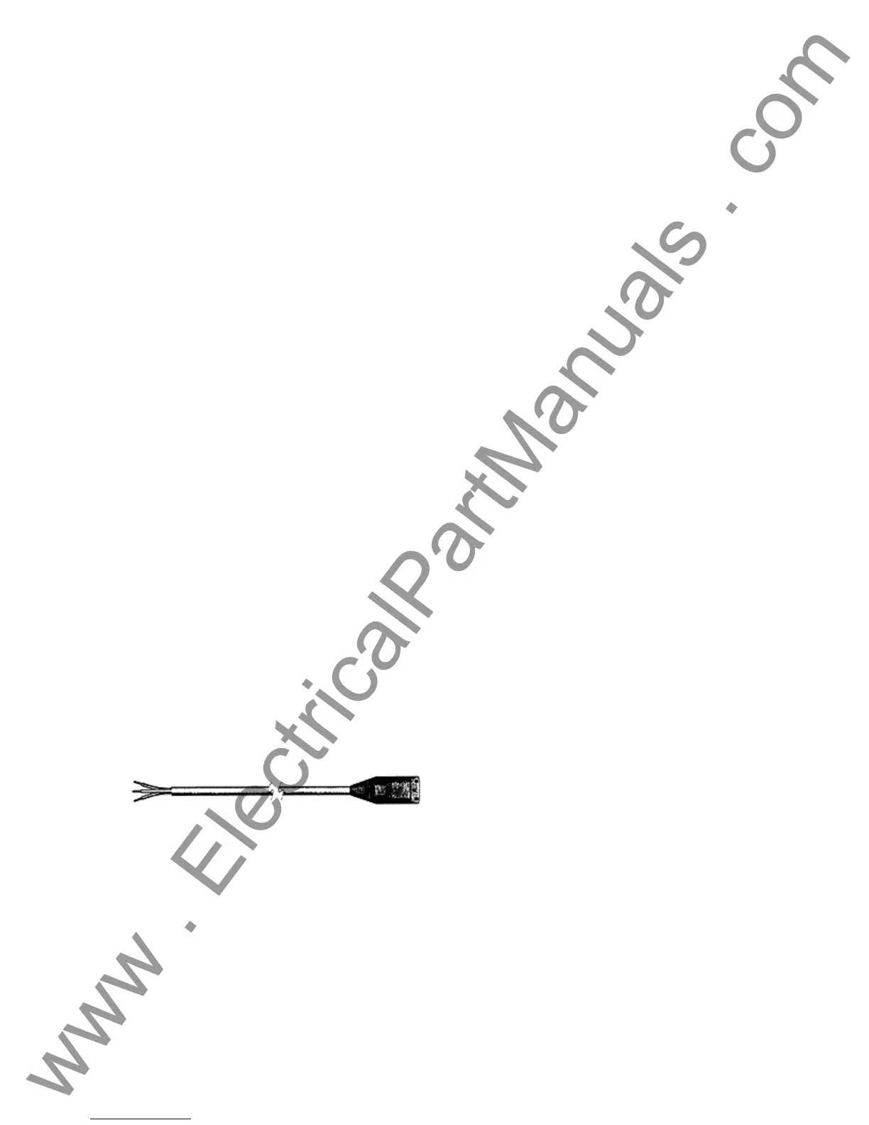
The 84XX-XXXXIX comes with a standard International Color code power cord as shown below.
The cord, part number 14525, is ready for wiring to the appropriate plug (depending on country).
The following colors apply, Brown = Line, Blue = Neutral and Green/Yellow = Ground.
Figure 5 International Color Coded Power Cord
1.4.2 Control Section
1.4.2.1 V/I Generator Module
The voltage and current ranges may be set to zero for automatic range adjustments or manually
set to the number desired in volts or amps as indicated below. The unit will choose the lowest
range which contains the desired value.
17
www . ElectricalPartManuals . com



 To Next Page