From the Law of Cosines
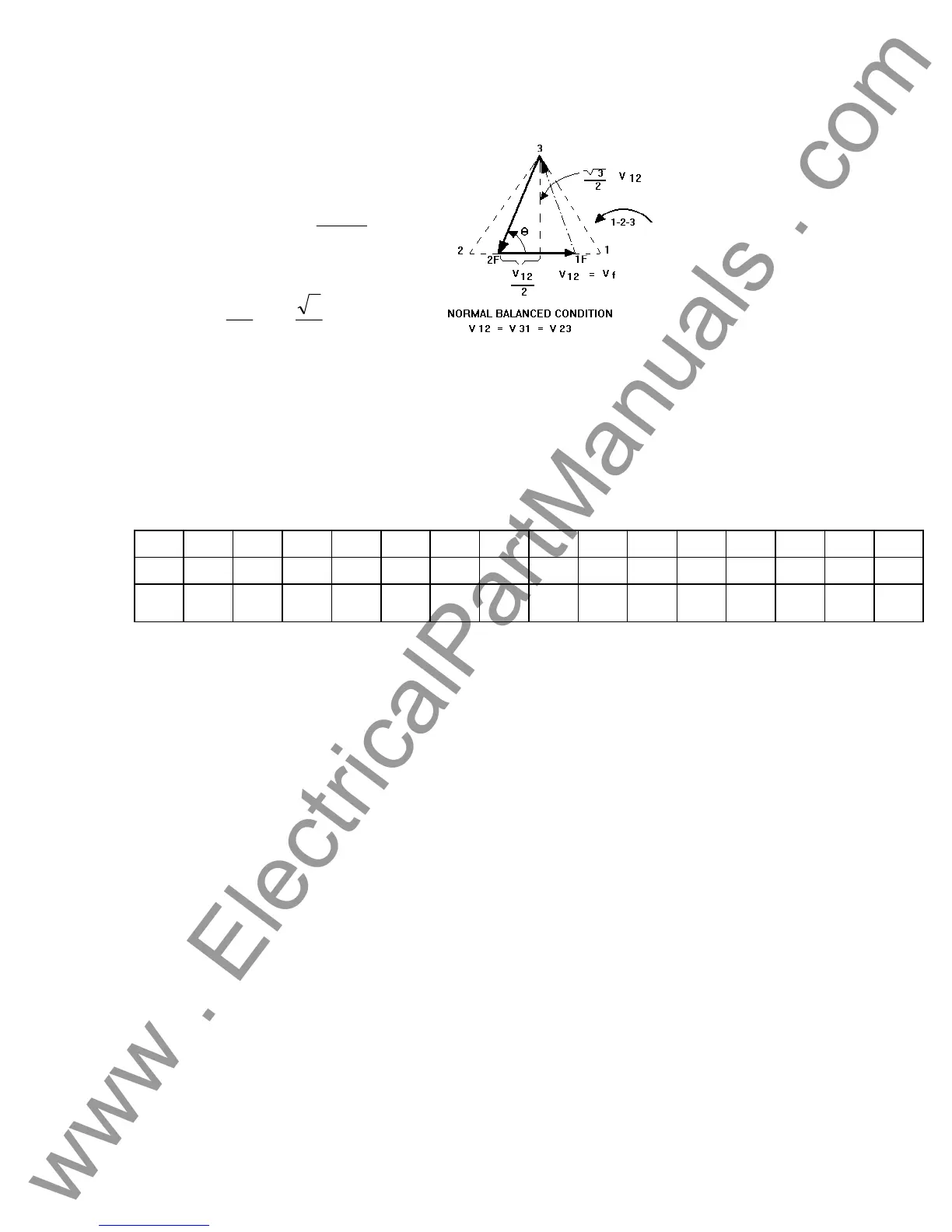
Figure 24 Open-Delta Unbalanced phase-to-phase Fault
Voltages
)
V2
V
(=
12
23
*
arccos
θ
23
2
12
22
V
=(
V
2
)
+(
3
2
*120
)
Settings For Typical Phase-to-Phase Fault Voltages
V
12
= V
f
V
12
1 5 10 15 20 25 30 35 40 45 50 55 60 65 70
V
23
104 104 104 104 104 105 105 105 106 106 106 108 108 109 110
At θ°
Lag
270 271 273 274 275 277 278 280 281 282 284 285 286 287 289
3.4.3.2 T Connection
The second method of obtaining a three-phase, three-wire voltage source is the so-called T-
Connection. The method, shown in the following figure, is easier to use when obtaining an
unbalanced, phase-to-phase fault simulation since it eliminates calculations. To reduce confusion
when using the T-Connection, the voltage output #1 is designated V
a
and its phase angle set at
0°, voltage output #2 is designated V
b
and its phase angle set for 180°, and voltage output #3 is
designated V
c
and its phase angle is set for 270 Any combination of balanced three phase faults
or unbalanced phase-to-phase fault conditions can be easily simulated. The following figure
indicates these phase relationships.
NOTE: This method should not be used for very low fault voltages (i.e. 5 volts or less, or for
testing ABB or Westinghouse type SKD relays).
37
www . ElectricalPartManuals . com
 Loading...