(positive) angles leading. Therefore, to set an angle of
+ 10° leading, the vector relationship
would be:
3.3 Current Sources
3.3.1 Parallel Operation
Two, three or four current channels may be connected in parallel to provide additional current
capacity. This is necessary when higher test currents are needed for testing instantaneous trip
elements.
To parallel the current channels of the unit, perform the following:
1. Note that all units with a style number T in the 7
th
digit (i.e. 8430L3T6A1) the current
commons are grounded. Those units with a style number F the current commons are
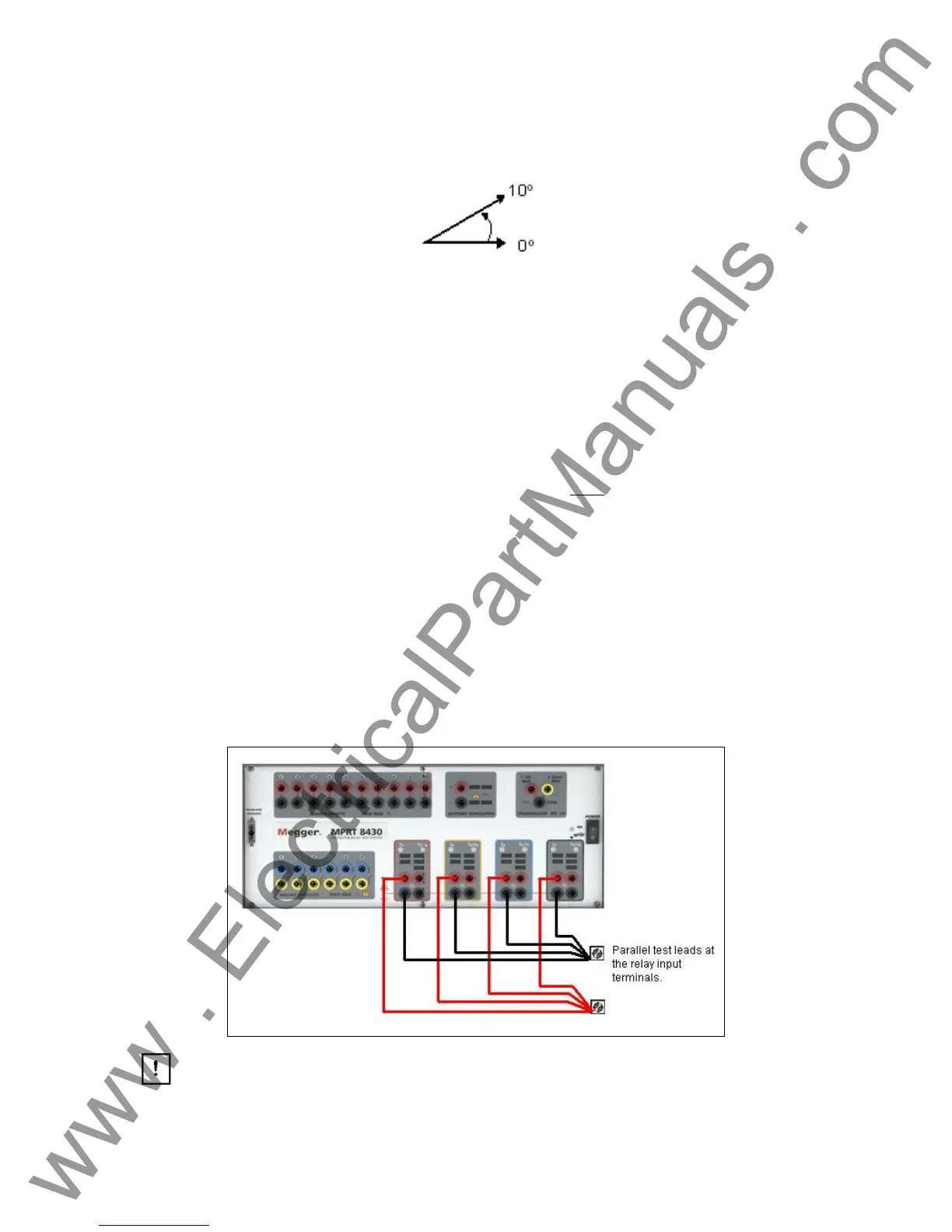
floating. Using the current channel test leads, connect each
current channel to the relay
under test (both red and black terminals to the load). Obviously, for the floating common
units you have to connect the black common return to the relay or there would not be any
current flow from that channel. By connecting the commons together, all of the current
channels would then have a common reference point. For the grounded common return
units, there is an internal common ground between the current channels. By not
connecting a return lead to all of the current channels in use, part or all of the return
current will be forced through the internal ground. That means with a 4 channel unit up to
120 Amperes could be forced through the internal common ground. Because of size and
weight restrictions, the unit is protected internally against too high of a current through the
common ground using surface mounted fuse type elements. Blowing a ground fuse
element will require the unit be returned to the factory for repair! Therefore, it is important
that the parallel connections must be made at the relay, not at the source through the
common ground return. See the following figure.
Figure 22 Parallel of All Four Current Outputs
NOTE: All current channels should be set to the same phase angle.
31
www . ElectricalPartManuals . com



 To Next Page