Complex Timer Setup Menu
Description
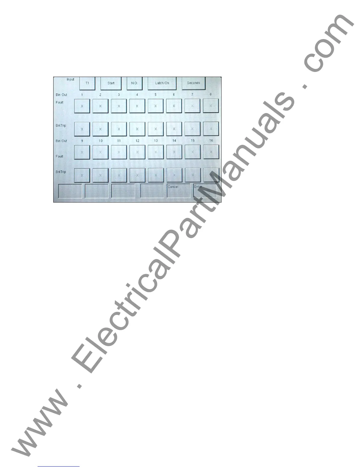
Figure 27 Complex Timer Setup and Binary Output Screen
Up to 16 different timers are available using the button labeled T1. This button will present a pull
down menu to select the required timers.
This screen will be used by the default screen to set system defaults. The time selection, when
used from the default screen, will set the time base for all screens. If seconds are selected, all
screens will set Duration, Op. Time, and Pulse Time to indicate seconds or milliseconds, as
applicable. If cycles are selected, the time base will be set to cycles. When this display is called
from a setup screen, the time base for the timer in that screen may be changed.
3.7 Battery Simulator
There are two distinct buttons for the Battery Simulator: the Volts DC and value settings. The
Battery Simulator output voltage can be set to 24, 48, 125, or 250 volts DC with the factory
default set at 125 VDC. This establishes the voltage values, but does not turn the Battery
Simulator power ON. The various test setup screens will allow the Battery Simulator to be
powered ON, as applicable.
3.8 Relay Testing
The Touch View Interface contains three user interfaces in one unit, a color LCD alphanumeric
display panel, a control knob, and a touch panel used to input data into the unit. The TVI will
display all active generator settings in red and all inactive, generator OFF, settings in green. If an
entered value is out of range, the display will be yellow and an Error Screen will appear. The
control knob will change the contents after the value is highlighted by touching the display with
your finger.
NOTE: The unit contains factory default values to run a quick test without entering data.
However, a one-time warning message will notify the user the test is being conducted with factory
default values if the defaults are used.
47
www . ElectricalPartManuals . com