3.8.6.2.1 Testing Sync-Check, Synchronizing and Auto-Synchronizing Relays
To perform tests on synchronizing type relays requires the use of two voltage output modules.
Pick-up or Closing Angle Tests: To perform Pick-up or Closing Angle tests let one voltage
channel be the 0° reference, i.e., V1, and let the second voltage channel provide the variable
phase angle adjustment, i.e., V2. This test requires phase angles indicated on V2 will be a
leading angle (this requires +/- 180° phase angle option). If the relay's closing characteristic is
20° leading, an angle of + 20° will be indicated on voltage channel 2 (assuming V1 is set to the 0°
reference).
Set V1 and V2 to Normal Voltage, i.e. 120 Volts each, and turn outputs on.
Ramp V2 phase angle in the CW direction lagging the reference voltage. At some point a set of
contacts may open, thus allowing the user to determine the dropout angle (- 20°). If the user
selected Normally Closed open, he could automatically capture this angle. The user could set the
starting angle of – 30° for V2, thus the contacts would not be closed. If we started the ramp at this
point the angle would continue to 180°. Then the sign would change to +. When the relay
Normally Open contacts closed we would capture the closing angle, i.e. + 20°. We would then
compare the actual closing angle to that specified in the Relay Setting Screen and calculate the
error in degrees.
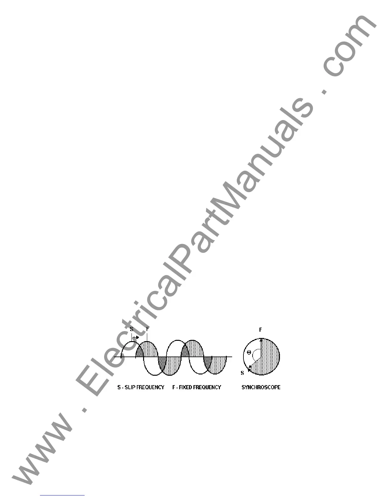
Setting Advance Time: To perform this test let voltage channel 2, V2, provide the slip frequency
(generator) and let voltage channel 1, V1, provide the fixed voltage/frequency source (bus).
Connect the relay's closing contacts to Timer Start Terminal 1 (first pair of Binary Input terminals),
so that when the relay contacts close (at the advance angle) it will start the timer, and capture the
closing angle at the same time. Set V1 to the Normal voltage output. Set V2 to the Normal output
voltage output and slip frequency. For example: VOLTAGE, 2, AC, 120, FREQ, 60.100. V2
ANGLE display should start at 0° (we want V1 and V2 to turn on at 0° together). V2 will turn on in
phase with V1, but will slip out of phase at the selected slip frequency. Since the phase angle is
measured, the angle should start to change for V2 reading a - number until the angle of 180° is
reached, then change to + . The number should fall from + 179° towards the closing angle At the
advance angle the relay contacts will close, thus starting the timer. Since the phase angle was
changing with the slip, we could capture the closing angle, when we start the timer. When the two
voltages slip into phase the Timer will stop. The time indicated will be the advance time setting of
the relay. See the following figure for a graphic representation.
As "S" approaches "F", at some point (the advance angle) the relay will send a close signal,
which will start the Timer. When "S" and "F" are in synchronous, the Timer will stop. The time
indicated on the timer display is the advance time of the relay based on the preset slip frequency.
-
92
www . ElectricalPartManuals . com