3.4 Voltage Sources
3.4.1 Outputs Summed Together
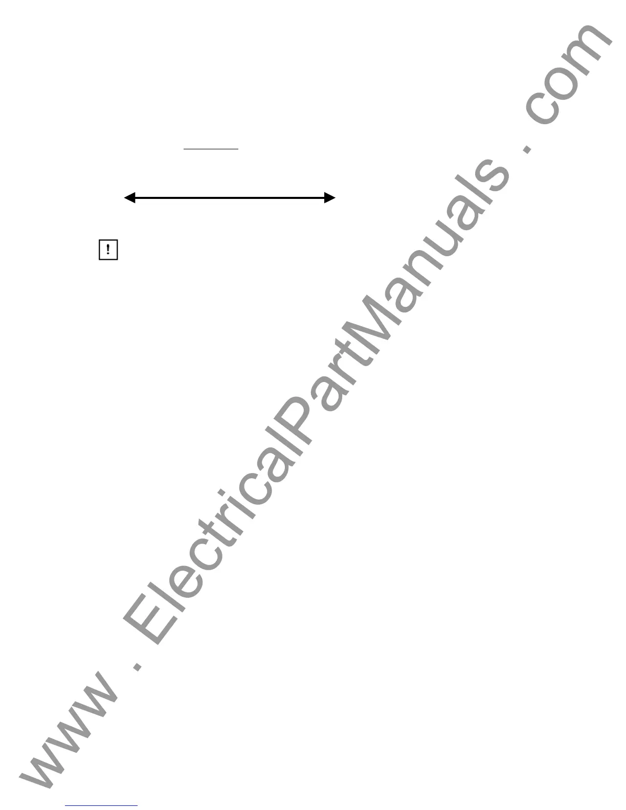
Two voltage channels may be used to sum the voltage outputs to obtain higher than rated voltage
provided the load is ungrounded
. Connect the load between the voltage channel posts, set V
1
Phase to 0° and set V
2
Phase to 180°. The voltage outputs will add so the total voltage is the
sum of the two voltage amplitudes, V
1
and V
2
as can be seen in the picture below.
V2
•
V1
.
Note that all units with a style number T in the 7
th
digit (i.e. 8430L3T6A1) the voltage
commons are grounded. For the grounded common return units, there is an internal common
ground between the voltage channels. Those units with a style number F the voltage commons
are floating. For the floating common units you have to connect the associated voltage channels
black common returns together, when series operation is required. Remove external commons
when testing is completed. DO NOT attempt to series more than two voltage channels together.
3.4.2 Dynamic Voltage Relay Test
Over/Under Voltage Relays can be dynamically tested using one voltage channel along with the
timer. This procedure applies a "normal”" voltage to the relay under test, then automatically
adjusts the test voltage to a "fault" amplitude that is higher (over voltage) than the pickup voltage.
The same is true for testing under voltage relays except the test voltage is dropped below the
relay pickup voltage. Additionally, the timer is automatically started with "fault" voltage applied to
the relay under test.
First, set the "normal" voltage on the relay, then with the relay energized to normal condition, set
the desired "fault" voltage and Timer Start (relay trip circuit should be connected to the Timer
Stop terminals). If you want to de-energize the voltage to the relay when it trips, use the Auto-Off
feature. The Timer starts, the relay trips, and stops the Timer. It then removes power from the
outputs. See Voltage Relay in section 3.8.5.
3.4.3 3Ø, 3-Wire, Open-Delta and T-Connection
3.4.3.1 Open Delta
Two methods of obtaining a three-phase, three-wire voltage source are available. The Open-
Delta configuration, referenced in the following figure, is the easier to use when a balanced three-
phase source and it is required because the amplitude and phase relationship can be set directly.
No calculations are necessary.
When using the Open-Delta Configuration to set up a phase-to-phase fault, calculations’ using
the Law of Cosines is required to calculate amplitude and phase relationships. (See discussion
under T-Connection for simulating unbalanced, phase-to-phase faults without need for
calculations.)
When using the Open-Delta configuration, it is suggested to use voltage channel #1, designated
V
1
, and voltage channel #2, designated V
2
, while the COMMON binding post is designated V
g
.
With this arrangement, the magnitude and phase angle of the potentials can be easily calculated
and set. For the balanced three-phase condition V
1g
and V
2g
are equal in magnitude and
35
www . ElectricalPartManuals . com