Normal Volt The Normal Volts is the desired test voltage per
phase. See Formula below for further
description.
Target Tap This value is the target tap setting. This value is
either 0.2 A or 2.0 A.
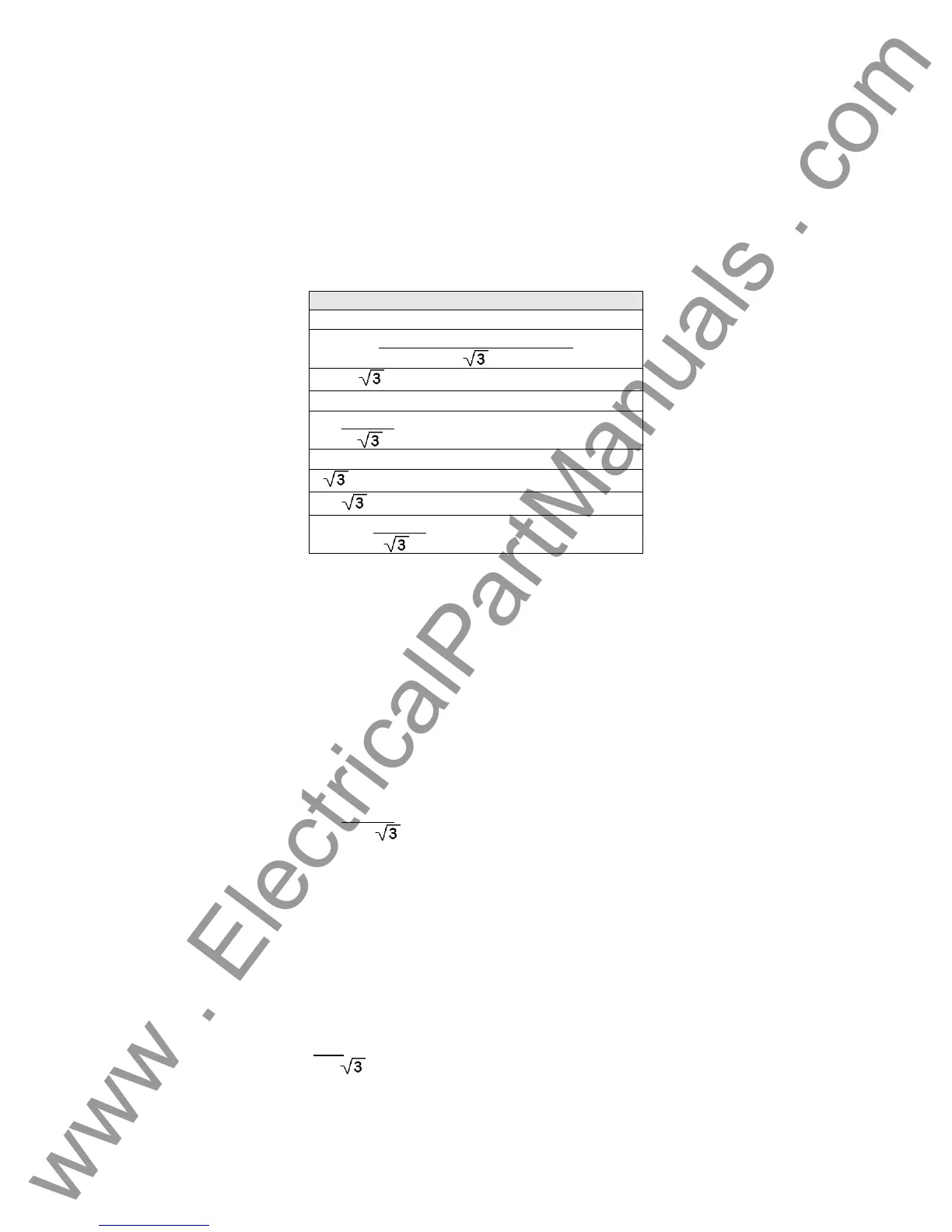
Formula There are several formulas that comprise the
Power Relay testing process as indicated below:
Formula’s
Voltage * Current * Cosine θ
Voltage * Current * Cosine θ
* Voltage * Current * Cosine θ
3 * Voltage * Current * Cosine θ
Voltage
θ1
-
θ2
* Current * (Cosine θ - 30˚)
Voltage
θ1
-
θ2
* Current * Cosine θ
* Voltage
θ1
-
θ2
* Current * (Cosine θ - 30˚)
* Voltage
θ1
-
θ2
* Current * Cosine θ
Voltage
θ1
-
θ2
* Current * Cosine θ
Each formula represents different types and styles of relays and how they are connected to the
power system. The formula selected will be used to calculate the Watts displayed in the test
screen. Some are used with single-phase relays for both Watt and VAR applications, where the
relay is calibrated in single-phase Watts. Some formulas represent other special applications
where the relay is a single phase relay sensing phase to phase voltage and single phase current,
or two phase current. One is for three phase voltage and two phase current applications, while
another is for three phase voltage and current, 4-wire Y connections. Another is for loss of
excitation relay calibrated in Watts. In the Power Relay Setting Screen, the Normal Volt is the
desired test voltage per phase. Under most single phase applications that would be considered a
phase to ground voltage. However, for single phase relays with the potential coil connected
phase to phase, and if the relay has a 30˚ lagging phase shift built into the voltage input circuit,
the formula
Voltage
θ1
-
θ2
* Current * (Cosine θ - 30˚)
will consider the Normal Volt set in the Relay Setting Screen as the phase to phase voltage, and
takes into account the 30˚ phase shift to calculate Watts. Therefore, it is important that the user
consider the relay design, application, the relay manufacturers recommended test connections,
relay settings and select the appropriate formula accordingly. For the above example, the
manufacturer has the user apply a single phase voltage equal to the phase to phase value, with a
single phase current lagging the voltage by 30˚. For this example let us assume a voltage value
of 120 volts phase to phase. The technician would enter 120 volts into the Normal Volt window. If
the relay pickup setting is 180 Watts, then we would expect the relay to operate at about 2.59
Amperes,
120
* 2.595 * (Cosine 30˚ - 30˚) = 180 Watts
where θ is the lagging angle of the test current.
-
96
www . ElectricalPartManuals . com
 Loading...