80
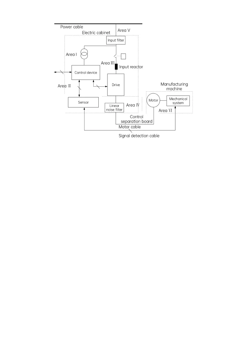
Fig. 4-36 Recommended partition for drive EMC installation
Notes:
Area Ⅰ: the control power transformer, control system, sensor, etc.
Area Ⅱ: the interface for the signal and control cables, requiring certain degree of anti-interference.
Area
Ⅲ
: the incoming reactor, drive, braking unit, contactor and other noise source.
Area Ⅳ: the output noise filter and its wiring.
Area Ⅴ: the power supply (including the radio noise filter wiring)
Area Ⅵ: the motor and its cables
There shall be space isolation among areas to realize electromagnetic decoupling.
The minimum spacing between areas shall be 20 cm.
The areas shall be decoupled via the grounding plate. Cables of different areas shall be put into different cable
conduits.
The filters shall be installed at the joints between areas.
All communication cables (such as RS485) and signal cables extending out from the cabinet shall be shielded.
 Loading...